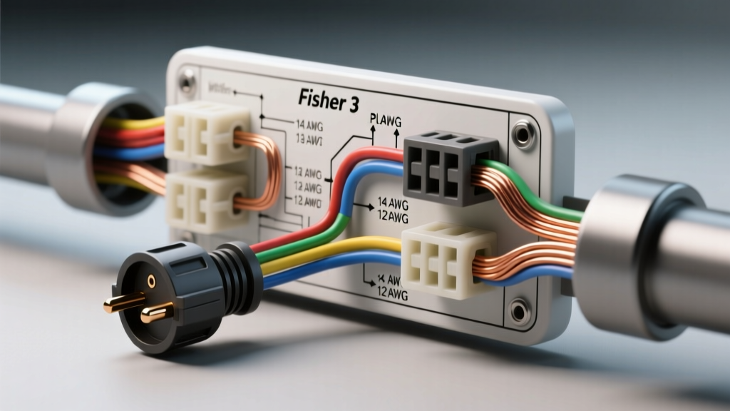
Understanding the Fisher 3-Plug Plow-Side Architecture
When executing a snowplow electrical modification or restoring a used Fisher Minute Mount 2 (MM2) setup, mastering the Fisher 3 plug wiring diagram plow side is critical. Unlike the newer 4-plug multiplex systems that rely on digital node communication, the legacy 3-plug system utilizes dedicated, hardwired circuits for power, lighting, and hydraulic control. While robust, the OEM plow-side harness is notorious for capillary corrosion—where moisture wicks between the wire insulation and copper strands, eventually destroying the molded bulkhead connector.
This guide details a comprehensive plow-side harness upgrade project. We will replace failing OEM wiring with automotive-grade GXL (cross-linked polyethylene) wire, upgrade the power delivery to mitigate cold-weather voltage drop, and transition from the failure-prone molded bulkhead to a sealed, serviceable junction architecture. Whether you are adapting a mismatched plow to your truck-side harness or rebuilding a degraded system, these specifications will ensure OEM-plus reliability.
Plug 1: Heavy-Duty Power and Ground Upgrades
The first plug in the 3-plug configuration is the heavy-duty power connector, typically featuring two massive, weather-sealed contacts. This circuit delivers direct battery power to the hydraulic pump motor (usually a Bosch or Haldex unit) and provides the primary ground path.
Wire Gauge and Material Upgrades
The OEM harness often utilizes 4 AWG copper wire. However, under heavy hydraulic load (such as angling the blade against a dense snowbank), the motor can draw upwards of 180 amps. In sub-zero temperatures, resistance increases, leading to severe voltage drop. For this upgrade, we mandate the use of 2 AWG GXL wire. GXL wire features a thinner, highly abrasion-resistant cross-linked insulation compared to standard PVC, allowing for tighter routing and superior heat dissipation.
- Positive Feed (Red): 2 AWG GXL, routed from the truck-side solenoid to the plow-side motor stud.
- Ground Return (Black): 2 AWG GXL, bonded directly from the motor housing to a dedicated, bare-metal star-washer grounding point on the main plow frame.
Pro-Tip: Do not rely on the pivot pins or hinge bolts for the ground path. The grease and paint on these moving parts create high-resistance bottlenecks. Always run a dedicated 2 AWG ground wire and torque the motor lugs to 120 in-lbs, sealing them with liquid electrical tape or marine-grade heat shrink.
Plug 2: 11-Pin Lighting Harness Pinout & Modification
The second plug handles all DOT-required lighting, including headlights, turn signals, and marker lights. The Fisher 3-plug lighting connector is typically an 11-pin rectangular configuration. Upgrading this harness requires strict adherence to the OEM pinout while improving the sealing methodology.
11-Pin Lighting Connector Pinout
| Pin | Function | OEM Wire Color | Upgrade Wire (GXL) | AWG |
|---|---|---|---|---|
| A | Ground (Common) | White / Black | Black | 14 |
| B | Park / Tail / Marker | Brown | Brown | 16 |
| C | Left Turn / Stop | Yellow | Yellow | 16 |
| D | Right Turn / Stop | Green | Green | 16 |
| E | Headlight Low Beam | White / Blue | White/Blue Tracer | 14 |
| F | Headlight High Beam | White / Red | White/Red Tracer | 14 |
| G | Left Marker Light | Brown / White | Brown/White Tracer | 18 |
| H | Right Marker Light | Brown / Yellow | Brown/Yellow Tracer | 18 |
LED Upgrade Considerations: If you are upgrading the plow headlights from Halogen (H13 or 9006/9005) to LED pods or sealed beams, the plow-side harness must be modified to handle the CANbus or PWM (Pulse Width Modulation) signals from modern trucks. Because LEDs draw significantly less current, the truck-side lighting control module may interpret the circuit as "open" and trigger a hyper-flash or dash error. To resolve this without splicing into the truck side, install inline CANbus anti-flicker resistors (typically 6-ohm, 50W) on the plow side, directly behind the headlamp bezels, ensuring they are mounted to a heat-sink area of the pushframe.
Plug 3: Hydraulic Solenoid Control Pinout
The third plug is the brain of the plow side, carrying low-amperage 12V trigger signals from the truck-side controller to the hydraulic valve manifold solenoids (S1, S2, S3, S4). This is typically a 12-pin or 11-pin connector depending on the exact valve bank (e.g., EZ-V vs. straight blade). Below is the standard 12-pin control layout for a typical Fisher 3-plow setup.
Solenoid Control Pin Configuration
| Pin | Circuit Function | Wire Color Code | Target Component |
|---|---|---|---|
| 1 | Control Ground | Black | Manifold Common Ground |
| 2 | S1 Trigger (Raise) | Red / White | S1 Solenoid Coil |
| 3 | S2 Trigger (Lower) | Red / Blue | S2 Solenoid Coil |
| 4 | S3 Trigger (Left Angle) | Red / Yellow | S3 Solenoid Coil |
| 5 | S4 Trigger (Right Angle) | Red / Green | S4 Solenoid Coil |
| 6 | Quench / Diode Return | Black / White | Suppressor Diode Network |
Diagnostic Insight: When testing the plow-side control harness, use a digital multimeter to measure the resistance across the solenoid coils. A healthy Fisher solenoid coil should read between 4.0 and 8.0 ohms. If you read 0 ohms, the coil is internally shorted and will blow the truck-side control fuses. If you read infinite resistance (OL), the coil is open. Never use a standard test light on these circuits, as the inductive kickback from the collapsing magnetic field can damage the truck-side multiplex node or controller.
The Core Modification: Eliminating the Molded Bulkhead
The most common failure point in the Fisher 3 plug wiring diagram plow side is the molded rubber bulkhead where the individual wires enter the main harness sheath. Over time, thermal cycling and road salt cause the rubber to micro-crack. Water enters and travels via capillary action deep into the harness.
Step-by-Step Bulkhead Bypass
- Excise the OEM Bulkhead: Cut the harness 12 inches behind the plug heads. Strip back the outer loom and remove the molded rubber junction.
- Prepare the Wires: Strip 5/16" of insulation from each GXL upgrade wire. Do not nick the copper strands.
- Hex-Crimp Terminals: Use open-barrel, mil-spec Deutsch or Weather-Pack terminals. Crimp using a precision hex-crimping tool (not standard pliers) to ensure a gas-tight mechanical bond.
- Install a Sealed Junction Block: Instead of re-molding the harness, route the plug pigtails into a marine-grade, epoxy-filled junction box (such as a Blue Sea Systems or custom ABS enclosure). Alternatively, transition each circuit into individual Deutsch DTM series sealed connectors. This allows you to unplug individual circuits at the plow frame for future troubleshooting without cutting wires.
- Potting and Sealing: Fill the junction enclosure with marine-grade potting compound or use dual-wall adhesive-lined heat shrink (3M FP-301) on every individual splice. The adhesive melts and seals the wire insulation, completely halting capillary moisture migration.
Troubleshooting Voltage Drop & Ground Faults
After completing the plow-side harness upgrade, perform a loaded voltage drop test. Connect the plow to the truck and engage the hydraulic pump (e.g., hold the "Raise" button). Using a multimeter, place the positive probe on the battery positive terminal and the negative probe on the motor positive stud. A reading above 0.5 volts indicates excessive resistance in the power cable or truck-side solenoid contacts. Repeat on the ground side; a drop greater than 0.2 volts on the ground circuit requires re-terminating the frame ground.
For the lighting circuits, apply Nyogel 760G dielectric grease to all plug pins before mating. Unlike standard silicone grease, Nyogel is specifically formulated to maintain conductivity while displacing moisture, preventing the galvanic corrosion that plagues aluminum and copper interfaces in winter environments.
Authoritative References
- For wire insulation and temperature rating standards, refer to the SAE J1128 Low Tension Primary Cable Specification, which dictates the requirements for GXL/TXL wire in harsh automotive environments.
- For OEM pinout verification and torque specifications on hydraulic components, consult the Fisher Engineering Technical Bulletins and Mechanic Guides specific to your MM2 or EZ-V serial number.