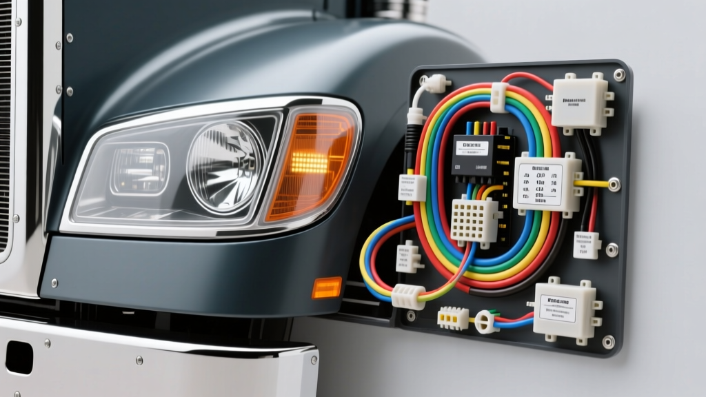
Understanding the Peterbilt 379 Lighting Architecture
The Peterbilt 379 is an iconic heavy-duty platform, renowned for its classic long-nose styling and extensive customization potential. However, when owner-operators decide to modernize their rigs with high-output LED headlights, auxiliary light bars, or chrome bezel-integrated turn signals, the factory electrical system often becomes a bottleneck. Understanding the OEM Peterbilt 379 headlight wiring diagram is critical before cutting, splicing, or adding relays. Unlike modern multiplexed systems found in newer Cascadias or late-model Kenworths, the classic 379 (particularly pre-2004 models) relies on a traditional analog relay and bulkhead routing system. While robust, this system was designed for the electrical draw of sealed-beam halogens, not the sensitive solid-state drivers of modern LEDs or the high inrush currents of HID ballasts.
In this comprehensive upgrade guide, we will break down the factory headlight circuit, identify the notorious failure points in the cab-to-chassis bulkhead, and provide a complete schematic for installing a heavy-duty relay bypass harness. This project ensures your upgraded lighting receives full system voltage, eliminating the dimming and flickering that plagues poorly executed modifications.
OEM Peterbilt 379 Headlight Wiring Diagram Breakdown
Before modifying the system, you must trace the factory current path. In a standard non-multiplexed Peterbilt 379, the headlight circuit originates at the main battery bank (typically a 4-battery 12V setup), passes through a heavy-duty fusible link or maxi-fuse, and enters the cab through the main bulkhead connector. From there, it feeds the dashboard headlight switch, routes to the floor-mounted or column-mounted dimmer switch, and travels back out through the bulkhead to the front chassis harness and headlight pigtails.
According to standard SAE J1292 automotive electrical wiring codes, heavy-duty trucks utilize specific color-coding for lighting circuits to maintain consistency across chassis manufacturers. Below is the standard wire color reference for the 379's primary headlight feeds.
| Wire Color | Function | Standard AWG | Circuit Path |
|---|---|---|---|
| Red / Red-White Trace | Constant Battery Feed (B+) | 10 AWG | Battery to Headlight Switch |
| Light Green | Low Beam Feed | 12 AWG | Dimmer Switch to Headlights |
| Dark Blue | High Beam Feed | 12 AWG | Dimmer Switch to Headlights |
| Black | Chassis Ground | 10 AWG | Headlight Pigtail to Frame Stud |
The Problem with the OEM Headlight Switch
The most common failure mode on the 379 platform is the melting of the headlight switch connector. The factory switch is designed to carry the full amperage of the headlights (approx. 10-12 amps for dual halogens). Over time, resistance builds at the switch terminals due to vibration and thermal cycling. When you upgrade to high-draw auxiliary lights or cheap LEDs with poor internal drivers that cause inrush spikes, the OEM switch overheats, melting the plastic housing and causing intermittent low-beam failures.
The Upgrade Project: Installing a Relay Bypass Harness
To protect your dash switch and guarantee maximum voltage to your new Truck-Lite or Grote LED headlights, you must remove the high-amperage load from the dashboard entirely. We achieve this by building a relay bypass harness. The OEM headlight switch will only act as a low-amperage trigger signal, while heavy-duty Bosch-style relays handle the actual current draw directly from the battery.
Relay Pinout and Wiring Specifications
For this project, use two 40A weather-sealed ISO mini relays (one for low beam, one for high beam). Ensure you purchase relays with an integrated suppression diode to prevent back-EMF voltage spikes from damaging your LED drivers when the circuit is switched off.
| Relay Pin | Function | Wire Color / Size | Connection Point |
|---|---|---|---|
| 30 | High Current Input | Red / 10 AWG | Direct to Battery Positive (via Inline Maxi-Fuse) |
| 87 | High Current Output | Red-White / 12 AWG | To Headlight Low/High Beam Pins |
| 86 | Trigger Input (+) | Light Green / Dark Blue / 16 AWG | Spliced into OEM Dimmer Switch Output |
| 85 | Relay Ground | Black / 14 AWG | Clean Chassis Ground Stud |
Step-by-Step Wiring Execution
Executing this upgrade requires attention to detail, particularly regarding wire gauge sizing and environmental sealing. The front of a Peterbilt 379 is subjected to extreme thermal cycles, road salt, and high-pressure washdowns.
- Mount the Relays: Locate a sheltered area behind the grille or on the inner fender well, away from direct exhaust heat and road debris. Use stainless steel hardware and apply anti-seize to prevent galvanic corrosion.
- Run the Main Power: Run a continuous 10 AWG primary wire from the positive battery post to Pin 30 on both relays. Install a 30A inline MAXI-fuse within 6 inches of the battery terminal to protect the main feed.
- Tap the Trigger Wires: Locate the Light Green (Low) and Dark Blue (High) wires exiting the cab bulkhead. Use military-grade heat-shrink solder sleeves (not butt connectors) to splice 16 AWG trigger wires to the OEM harness. This provides the trigger signal to Pin 86 on your new relays.
- Route the Load Wires: Run 12 AWG wires from Pin 87 to your new LED headlight pigtails. If your 379 uses the standard 3-prong H4 or sealed beam plugs, use ceramic adapters to prevent melting.
AWG Wire Sizing for Heavy-Duty Runs
Voltage drop is the enemy of LED performance. Even a drop of 1.5V can cause LED drivers to shut down or flicker. Use the following chart to size your wires based on the total length of the run (positive + negative) from the battery to the headlights and back to ground.
| Total Wire Run Length | 10 Amp Load (Standard LED) | 20 Amp Load (Aux/HID) |
|---|---|---|
| 0 - 10 Feet | 14 AWG | 12 AWG |
| 10 - 20 Feet | 12 AWG | 10 AWG |
| 20 - 30 Feet | 10 AWG | 8 AWG |
Tackling the Cab-to-Chassis Bulkhead Connector
The 70-pin cab-to-chassis bulkhead connector is the Achilles heel of the Peterbilt 379 electrical system. Located on the firewall, this connector bridges the cab harness and the chassis harness. Over years of highway vibration and moisture intrusion, the pins oxidize, leading to severe voltage drop and localized heating.
When performing a headlight upgrade, inspect the bulkhead pins corresponding to the Light Green and Dark Blue circuits. If you see green/white corrosion or melted plastic cavities, you must repin the connector. Extract the damaged terminals using the proper Deutsch or Amphenol extraction tool. Crimp new nickel-plated terminals using a ratcheting crimp tool (never pliers), and pack the connector cavities with a high-dielectric silicone grease, such as Amphenol DeoxIT, to displace moisture and prevent future oxidation.
Troubleshooting Common 379 Headlight Issues Post-Upgrade
Even with a perfect wiring diagram and relay harness, owner-operators frequently encounter specific issues when retrofitting modern lighting onto legacy platforms. Here is how to diagnose and fix them:
1. Hyperflashing and Dash Warning Lights
If your 379 utilizes a body controller or flasher module that relies on thermal resistance or amperage draw to dictate flash rate, switching to low-draw LEDs will cause the turn signals to hyperflash. The fix is not to wire in cheap load resistors (which generate massive heat and defeat the purpose of LEDs). Instead, replace the OEM flasher relay in the fuse panel with a solid-state, LED-compatible electronic flasher module designed for heavy-duty trucks.
2. Ground Loop Flickering
LEDs are highly sensitive to voltage fluctuations. If your headlights flicker at idle but stabilize at highway RPMs, you likely have a poor ground connection at the chassis ground stud behind the battery box. Remove the ground cable, wire-brush the frame rail down to bare, shiny metal, apply a thin coat of dielectric grease, and torque the bolt to 35 lb-ft. Ensure the ground wire is upgraded to at least 8 AWG to handle the return current of the entire front lighting array.
3. PWM Interference on Late-Model 379s
Some late-production 379s (2005-2007) introduced early iterations of PACCAR multiplexing and Pulse Width Modulation (PWM) for dash lighting and headlight dimming. If your new LEDs strobe or fail to turn on fully, the OEM switch may be sending a PWM signal rather than a solid 12V DC signal. In this case, you must install a PWM-to-DC signal converter between the OEM trigger wire and your relay's Pin 86 to ensure the relay receives a clean, continuous 12V trigger.
Final Verification and Testing
Once all connections are sealed with adhesive-lined dual-wall heat shrink and secured with split-loom tubing, perform a voltage drop test. With the engine running and the high beams engaged, place your multimeter's red probe on the battery positive terminal and the black probe on the headlight positive pin. A reading above 0.2V indicates excessive resistance in your new wiring, requiring larger gauge wire or better crimp terminations. By strictly following this Peterbilt 379 headlight wiring diagram and upgrade protocol, you will achieve a reliable, blindingly bright lighting setup capable of enduring millions of highway miles.