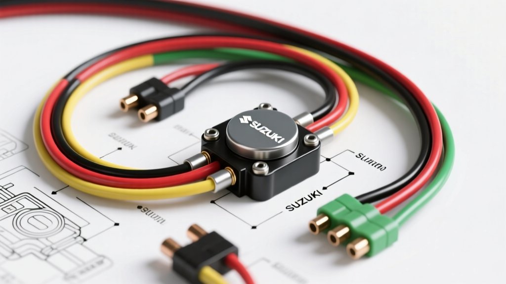
Understanding the Suzuki Ignition Architecture
For beginners entering the world of motorcycle electronics, the factory harness can look like an intimidating bowl of spaghetti. However, Suzuki has maintained a remarkably consistent electrical architecture across its most popular platforms—from the legendary GSX-R sportbikes to the versatile SV650 and DRZ400 dual-sports. Whether you are building a cafe racer, prepping a bike for track-day use where key tethers are a liability, or simply replacing a damaged barrel, understanding the core switching logic is essential.
When you first unroll a bypass ignition switch suzuki motorcycle wiring diagram, the maze of lines and symbols can feel overwhelming. The secret to mastering these schematics is realizing that the ignition switch on most traditional Suzuki motorcycles is not a complex computer module; it is simply a mechanical multi-pole bridge that routes battery voltage to specific circuits while simultaneously managing the engine kill ground. By breaking the diagram down into its fundamental components, you can safely and reliably bypass the key cylinder without compromising the bike's charging system or ECU.
Decoding the Bypass Ignition Switch Suzuki Motorcycle Wiring Diagram
A standard Suzuki ignition switch schematic typically features a 4-pin or 6-pin connector block. To read the diagram effectively, you must understand the flow of current from the battery, through the main fuse, into the switch, and out to the bike's sub-systems. In Suzuki factory service manuals, the diagram will show the switch in the 'OFF', 'ON', and 'PARK' positions, with shaded areas indicating internal mechanical continuity between the pins.
According to CMSNL Suzuki OEM Schematics, the core function of the switch is to bridge the constant 12V feed to the ignition and lighting circuits, while breaking the ground path to the CDI/TCI unit. If you are bypassing the switch for a custom build, your goal is to replicate the 'ON' position permanently using proper automotive-grade splices and connectors.
OEM Wire Color Codes and AWG Specifications
Suzuki adheres to strict Japanese Industrial Standards (JIS) for wire coloring. When consulting your wiring diagram, you will consistently encounter the following color codes. It is critical to match the American Wire Gauge (AWG) to the factory specifications to prevent voltage drop or, worse, a harness fire. We recommend using SAE J1128 TYPE SXL cross-linked polyethylene wire for all engine bay and harness replacements, as detailed in the SAE J1128 Standard for Low Tension Primary Cable.
| Wire Color | Function | Factory AWG | Circuit Destination |
|---|---|---|---|
| Orange (O) | Constant Battery Power | 14 AWG | Switch Input (from Main 30A Fuse) |
| Gray (G) | Switched Ignition Power | 18 AWG | ECU, Coils, Instruments, Kill Switch |
| Brown (Br) | Switched Accessory/Tail | 18 AWG | Tail Light, License Plate Light |
| Black/White (B/W) | Engine Kill Signal | 18 AWG | CDI/TCI Unit (Ground to Kill) |
Step-by-Step Bypass Execution for Track and Custom Builds
Bypassing the ignition switch requires more than just twisting wires together. A proper bypass ensures that the high-amperage circuits are handled safely and that the engine kill circuit is correctly isolated. On classic carbureted and early EFI Suzuki models, the Black/White wire kills the engine by providing a path to ground. Therefore, a successful bypass requires you to isolate the Black/White wire while bridging the power circuits.
- Disconnect the Battery: Always remove the negative terminal first to prevent shorting the main Orange wire against the frame.
- Locate the Main Harness Connector: Trace the wires from the ignition switch down to the main chassis harness. You will typically find a Sumitomo waterproof connector near the steering stem or under the fuel tank.
- Isolate the Kill Circuit: Cut the Black/White wire on the harness side (not the switch side, in case you ever want to revert). Cap the end with a piece of 3M Scotchlok or adhesive-lined heat shrink. Do not ground this wire, or the bike will never produce a spark.
- Bridge the Power Circuits: Using a 14 AWG butt connector or a proper solder-and-heat-shrink joint, bridge the Orange (Constant 12V) wire to the Gray (Switched 12V) wire. This tells the ECU and ignition coils that the key is in the 'ON' position.
- Handle the Tail Light (Optional): If you want your tail light to function, bridge the Orange wire to the Brown wire as well. For track bikes, you can simply cap the Brown wire to save parasitic draw.
- Secure the Harness: Wrap the modified section in Tesa cloth harness tape (not cheap vinyl electrical tape, which turns to adhesive slime in engine heat) and secure it away from the steering stem to prevent pinch points.
Sumitomo Connector Pinout and Crimping Standards
If you are building a custom harness from scratch rather than splicing into the OEM wires, you will need to interface with the factory ECU and fuse box. Suzuki relies heavily on Sumitomo HM 090 and MT 060 series waterproof connectors. According to Electrosport Industries Technical Info, using the correct crimping tool is non-negotiable. Pliers will crush the terminal, destroying the waterproof seal and leading to green corrosion inside the pin cavity. Invest in a dedicated Sumitomo ratcheting crimper (such as the IWS-1424) to ensure the wire bell-crimp and insulation crimp are perfectly formed.
Troubleshooting Matrix: Common Bypass Failures
Even with a perfect wiring diagram, beginners often encounter issues after executing a bypass. Use this decision tree to diagnose common no-start or electrical gremlins.
| Symptom | Probable Cause | Diagnostic Fix |
|---|---|---|
| Engine cranks but has zero spark. | Black/White wire is grounding out against the frame or was incorrectly spliced to ground. | Use a multimeter to check continuity between the B/W ECU pin and the chassis ground. It should read 'OL' (Open Loop). |
| Bike starts, but dash and lights are dead. | Orange to Gray bridge is solid, but the secondary accessory fuse is blown or Brown wire was omitted. | Check the 10A signal fuse in the main fuse box. Bridge Orange to Brown if tail lights are desired. |
| Bike runs, but voltage drops below 12V at high RPM. | Voltage drop across a poor-quality splice on the 14 AWG Orange wire. | Perform a voltage drop test across the splice. If >0.2V, cut and re-solder the joint using adhesive-lined marine heat shrink. |
| Steering lock prevents turning the bars. | Mechanical steering lock pin is still engaged in the triple tree. | Remove the triple tree, drill out the lock cylinder shear bolts, and physically remove the lock mechanism. Do not force the bars. |
Safety, Steering Locks, and Legal Warnings
While a bypass ignition switch Suzuki motorcycle wiring diagram is a fantastic resource for off-road, track, and show builds, it inherently disables the motorcycle's primary anti-theft deterrent. When bypassing the electrical switch, you must also address the mechanical steering lock. Forcing the handlebars while the lock pin is engaged will snap the pin inside the lower triple tree, requiring a complete teardown of the front end to extract the metal shard.
Furthermore, remember that a bypassed bike is 'always on' electrically. If you forget to install a secondary hidden kill switch or a battery tender disconnect, the ECU and instrument cluster will slowly drain the battery over a few weeks. Always install a heavy-duty 30A marine toggle switch in a hidden location to serve as your new master disconnect, ensuring your custom Suzuki build remains safe, reliable, and ready to ride.