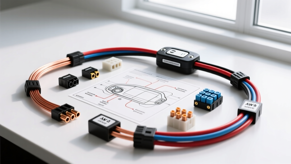
Understanding Automotive Access Control and Magnetic Locks
When transitioning from residential or commercial security to automotive electronics, the terminology can be confusing. In commercial buildings, an "access control magnetic door lock" usually refers to a high-voltage electromagnetic maglock that secures a door frame. However, in the automotive world, vehicles utilize electromagnetic solenoids (actuators) and magnetic reed switches to achieve the same access control functionality. Whether you are installing an aftermarket RFID immobilizer bypass, a Bluetooth smartphone-entry module, or a custom keypad, understanding the underlying 12V DC wiring diagram is critical.
This beginner-friendly guide breaks down the fundamental wiring logic required to integrate an aftermarket access control module (ACM) with your vehicle's electromagnetic door lock actuators and magnetic door-ajar sensors. By mastering these core concepts, you will be able to read, modify, and safely execute any vehicle-specific lock wiring schematic.
Core Components of the Wiring Diagram
Before splicing a single wire, you must identify the primary components involved in an automotive access control locking circuit. Unlike home wiring, automotive circuits rely on a chassis-ground return path and are highly susceptible to voltage spikes.
1. The Access Control Module (ACM)
The ACM is the brain of your system. It receives an encrypted signal (via RFID fob, BLE, or keypad) and outputs a low-current 12V trigger pulse. This pulse is typically limited to 200mA–500mA, which is not enough to drive a door lock actuator directly. Therefore, the ACM must trigger a relay or an H-bridge circuit.
2. The Electromagnetic Actuator (Solenoid)
Automotive door locks use 2-wire or 3-wire electromagnetic solenoids. A standard 2-wire aftermarket actuator draws between 3 to 5 amps momentarily. To lock and unlock, the polarity of the 12V and Ground wires must be reversed. This requires a specific relay configuration known as a polarity reversal circuit.
3. Magnetic Reed Switches
Advanced access control systems need to know if the door is physically closed before attempting to lock it, preventing the system from locking an open door. This is achieved using a magnetic reed switch mounted on the door jamb, paired with a rare-earth neodymium magnet on the door shell. When the door closes, the magnetic field collapses the reed switch contacts, sending a signal back to the ACM.
The Polarity Reversal Relay Diagram Logic
The most common stumbling block for beginners is attempting to wire a 2-wire lock actuator to a single standard 5-pin Bosch relay. A single relay can only provide power in one direction. To reverse polarity for lock and unlock functions, you must wire two 5-pin SPDT (Single Pole Double Throw) relays together to simulate a DPDT (Double Pole Double Throw) switch.
Wiring the Dual-Relay Lock/Unlock Circuit
- Relay 1 (Lock) & Relay 2 (Unlock) Pin 30: Connect to a fused 12V+ constant power source (14 AWG).
- Relay 1 & Relay 2 Pin 85: Connect to a clean, bare-metal chassis ground (14 AWG).
- Relay 1 Pin 86: Connect to the ACM's "Lock" trigger output (18 AWG).
- Relay 2 Pin 86: Connect to the ACM's "Unlock" trigger output (18 AWG).
- Relay 1 Pin 87: Connect to Relay 2 Pin 87a, AND to Actuator Wire A (14 AWG).
- Relay 2 Pin 87: Connect to Relay 1 Pin 87a, AND to Actuator Wire B (14 AWG).
- Relay 1 & Relay 2 Pin 87a: Connect to a shared chassis ground (14 AWG).
How it works: When the ACM triggers Relay 1, Pin 87 sends 12V+ to Actuator Wire A, while Pin 87a provides a ground path to Actuator Wire B. When Relay 2 is triggered, the polarity flips, reversing the electromagnetic field inside the solenoid and moving the lock linkage in the opposite direction.
Integrating Magnetic Reed Switches for Door Status
To wire the magnetic door sensor, you will use a simple switched-ground or switched-12V circuit, depending on your ACM's logic requirements. Most modern automotive security modules utilize a switched-ground (negative trigger) input for door status.
- Run an 18 AWG primary wire from the ACM's "Door Ajar" input to the door jamb.
- Connect one side of the glass-encapsulated magnetic reed switch to this signal wire.
- Connect the other side of the reed switch to a local chassis ground on the door frame.
- Mount the neodymium magnet on the moving door shell, ensuring a gap of no more than 1/4 inch (6mm) when the door is closed.
When the door opens, the magnet moves away, the reed switch opens, and the ACM sees an infinite resistance (open circuit). When the door closes, the magnetic field forces the reed contacts together, completing the ground circuit and telling the ACM the door is secure.
Wire Gauge, Color Codes, and Specifications
Adhering to SAE (Society of Automotive Engineers) standards for wire gauge and color coding ensures your installation is safe, serviceable, and fire-resistant. Below is the standard specification chart for an automotive access control locking circuit.
| Circuit Function | Recommended AWG | Standard Color Code | Max Current | Technical Notes |
|---|---|---|---|---|
| Main 12V+ Power (Relay Pin 30) | 14 AWG | Red | 15 Amps | Must include a 15A inline ATC fuse within 18 inches of the battery. |
| Main Chassis Ground (Relay Pin 85) | 14 AWG | Black | 15 Amps | Use a ring terminal and star washer on bare, unpainted metal. |
| ACM Lock Trigger (Relay 1 Pin 86) | 18 AWG | Blue/White | 0.5 Amps | Low current signal wire; keep away from high-voltage ignition wires. |
| ACM Unlock Trigger (Relay 2 Pin 86) | 18 AWG | Green/White | 0.5 Amps | Low current signal wire. |
| Actuator Motor Wires | 14 AWG | Blue & Green | 10 Amps | Use stranded copper (TXL or GXL type) to withstand door hinge flexing. |
| Reed Switch Signal | 20 AWG | Violet | 0.1 Amps | Use flexible silicone-jacketed wire where it passes through the door boot. |
Real-World Troubleshooting for Beginners
Even with a perfect diagram, real-world vehicle environments introduce electrical noise and physical stressors. Here are the most common failure modes and how to fix them:
1. Back-EMF and ACM Resetting
When an electromagnetic actuator is suddenly de-energized, the collapsing magnetic field generates a massive reverse voltage spike known as Back-EMF (Electromotive Force). This spike can travel back through the trigger wires and reset or fry your Access Control Module. The Fix: Always use relays with built-in internal suppression resistors, or solder a 1N4001 flyback diode across the actuator wires or relay coil pins (striped end facing 12V+).
2. Voltage Drop Across Door Hinges
If your lock actuator clicks but lacks the physical strength to move the latch, you likely have voltage drop. The flexible rubber boot between the door and the chassis is a notorious bottleneck. The Fix: Perform a voltage drop test with a digital multimeter while the lock is actuating. If you read more than 0.5V drop on the power or ground side, upgrade the wiring through the door hinge to 12 AWG and ensure your ground points are free of rust and paint.
3. Reed Switch False Triggers
If the ACM thinks the door is open when it is actually closed, the magnetic field may be too weak, or the reed switch is misaligned. The Fix: Ensure you are using a Neodymium (rare-earth) magnet, not a standard ceramic ferrite magnet. Standard ceramic magnets often fail to penetrate the thick steel of a vehicle door shell to trigger the reed switch reliably.
Authoritative References and Further Reading
To deepen your understanding of automotive electrical systems and electromagnetic compatibility, consult the following industry-standard resources:
- Automotive Relays and Circuit Fundamentals (Autoshop 101) - An essential guide to understanding 5-pin Bosch relay logic and polarity reversal.
- SAE J1113: Electromagnetic Compatibility (EMC) Standards - Critical reading for understanding Back-EMF, electrical noise, and shielding in vehicle access control modules.
- Bosch Mobility Solutions: Automotive Relay Specifications - Manufacturer datasheets detailing pin configurations, current ratings, and internal suppression diodes.