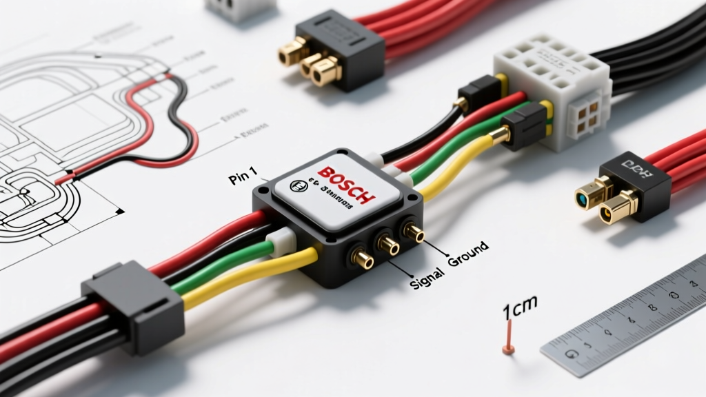
Introduction to DPF Differential Pressure Sensor Circuitry
The Diesel Particulate Filter (DPF) differential pressure sensor is a critical component in modern light-duty and heavy-duty diesel emissions systems. By measuring the pressure drop (Delta P) across the DPF substrate, the Powertrain Control Module (PCM) calculates the soot load and determines when to initiate active or passive regeneration cycles. For automotive electrical technicians, understanding the DPF sensor wiring diagram is essential for accurately diagnosing regeneration failures, limp-mode conditions, and false exhaust restriction codes.
Most modern applications, including the Ford 6.7L Powerstroke, Ram 6.7L Cummins, and GM 6.6L Duramax, utilize a piezoresistive differential pressure sensor manufactured by Bosch or Continental. These sensors contain a silicon membrane with integrated strain gauges arranged in a Wheatstone bridge configuration. As exhaust gas pressure deforms the membrane, the electrical resistance changes, yielding a linear analog voltage signal. Advanced 5-wire variants also include an integrated Negative Temperature Coefficient (NTC) thermistor to provide intake/exhaust temperature data for thermal compensation and density calculations.
Bosch 5-Wire DPF Sensor Pinout & Wiring Diagram Specifications
The following pinout configuration represents the industry-standard Bosch 5-way DPF differential pressure and temperature sensor, commonly found on Ford 6.7L Powerstroke applications. This reference maps the internal sensor pins to the PCM harness.
| Pin | Circuit Function | PCM Pin Reference | Wire Color (Ford 6.7L) | AWG / mm² | Terminal Type |
|---|---|---|---|---|---|
| 1 | DPFE Signal (Vout) | PCM Pin 42 | Brown/Orange (BRN/ORG) | 22 AWG (0.35) | TE Connectivity Sealed |
| 2 | Sensor Ground (RTN) | PCM Pin 18 | Black/White (BLK/WHT) | 20 AWG (0.50) | TE Connectivity Sealed |
| 3 | 5V Reference (VREF) | PCM Pin 11 | Brown/White (BRN/WHT) | 20 AWG (0.50) | TE Connectivity Sealed |
| 4 | DPF IAT Signal (Temp) | PCM Pin 56 | Grey/Red (GRY/RED) | 22 AWG (0.35) | TE Connectivity Sealed |
| 5 | IAT Sensor Return | PCM Pin 29 | Black/Yellow (BLK/YEL) | 22 AWG (0.35) | TE Connectivity Sealed |
Wire Color Codes & AWG Ratings Explained
Signal circuits (Pins 1 and 4) utilize 22 AWG (0.35 mm²) wire to minimize harness weight and bulk, while the 5V Reference and main Sensor Ground (Pins 2 and 3) use slightly thicker 20 AWG (0.50 mm²) wire to prevent voltage drop over the harness run. The 5V reference must remain stable at 5.0V ±0.1V; any voltage drop on the VREF circuit due to undersized wiring or corrosion will result in a skewed DPFE signal, causing premature or failed regenerations.
Signal Voltage Parameters & Transfer Functions
When backprobing the DPFE signal wire (Pin 1) with a high-impedance digital multimeter (DMM) or observing via an oscilloscope, the voltage should correlate linearly with the pressure differential across the filter. The PCM uses this transfer function to estimate soot mass in grams per liter (g/L).
| Differential Pressure (kPa) | Analog Signal Voltage (V) | PCM Soot Load Estimation | System State |
|---|---|---|---|
| 0.0 kPa (Key On, Engine Off) | 0.45V - 0.55V | 0 g/L | Baseline / Sensor Check |
| 10.0 kPa (Idle / Light Load) | 0.90V - 1.10V | 2 - 4 g/L | Normal Operation |
| 35.0 kPa (Highway Cruise) | 2.10V - 2.30V | 6 - 8 g/L | Passive Regen Threshold |
| 65.0 kPa (Heavy Load) | 3.40V - 3.60V | 10 - 12 g/L | Active Regen Trigger |
| > 95.0 kPa (Restricted) | > 4.70V | > 18 g/L | DTC P2463 / Limp Mode |
Note: If the KOEO (Key On Engine Off) voltage reads exactly 4.9V or 0.1V, the PCM has detected an open or short circuit, respectively, and will set a hard electrical fault code (e.g., P2453 or P2454) before the engine even cranks.
Harness Routing, EMI Shielding, and Thermal Constraints
Because the DPFE signal is a low-voltage analog waveform, it is highly susceptible to Electromagnetic Interference (EMI) and Radio Frequency Interference (RFI). When repairing or replacing a DPF sensor harness, adhere to the following SAE J1939 and OEM routing guidelines:
- Thermal Limits: The sensor electronics are rated for an ambient operating temperature of -40°C to +125°C. The harness must be wrapped in high-temperature fiberglass braided sleeving or corrugated nylon conduit rated for 150°C if routed within 6 inches of the exhaust downpipe or DPF canister.
- EMI Separation: Never route the DPFE signal wires parallel to the Fuel Injector Control Module (FICM) or injector PWM harnesses. Maintain a minimum 2-inch separation to prevent inductive cross-talk, which can cause erratic pressure spikes in the PCM data PID.
- Drip Loops: Always form a drip loop in the harness immediately before the connector mating face. This prevents capillary action from drawing moisture into the sealed TE Connectivity connector cavity during thermal cycling.
Diagnostic Decision Tree: DTC P2453 / P2454 Troubleshooting
When diagnosing DPF pressure sensor electrical faults, avoid piercing the wire insulation with test probes. Piercing creates micro-holes that allow moisture ingress, leading to copper oxidation and eventual PCM pin corrosion. Always use T-pin backprobes at the connector cavity.
- Step 1: Visual & Mechanical Inspection
- Inspect the silicone DPF pressure hoses for melting, cracking, or soot blockages.
- Verify the upstream (pre-DPF) and downstream (post-DPF) hoses are not swapped. Reversed hoses will cause a negative pressure reading at idle.
- Step 2: VREF Circuit Validation (Pin 3)
- Disconnect the sensor connector. Turn ignition ON.
- Measure voltage between Pin 3 (harness side) and battery negative.
- Spec: 4.8V to 5.2V. If 0V, check for open circuit to PCM or blown 5V reference fuse.
- Step 3: Ground Circuit Validation (Pin 2)
- Measure resistance between Pin 2 (harness side) and battery negative.
- Spec: Less than 0.5 Ohms. If > 5 Ohms, locate high-resistance splice or corroded PCM ground pin.
- Step 4: Signal Circuit Integrity (Pin 1)
- Check for continuity between Pin 1 (harness side) and PCM Pin 42.
- Check for short-to-ground and short-to-power on the signal wire.
- If wiring tests OK but KOEO voltage remains out of spec (0.5V ±0.1V), the internal Wheatstone bridge in the sensor has failed. Replace the sensor assembly.
Mechanical Installation & Torque Specifications
Improper mounting of the DPF sensor can induce mechanical stress on the silicon membrane, causing a zero-point offset error. When installing a replacement sensor:
- Mounting Bolts: M6 x 1.0 flange bolts. Torque to 8 - 10 Nm (71 - 89 lb-in). Do not over-torque, as this can warp the sensor housing.
- Hose Clamps: Use constant-tension spring clamps or high-temp T-bolt clamps. Torque T-bolt clamps to 2 - 3 Nm.
- PCM Relearn: After replacement, a DPF Pressure Sensor Offset Relearn procedure MUST be performed via a bidirectional OBD2 scan tool. This establishes the new baseline voltage at 0 kPa differential pressure.
Authoritative References & Service Manual Citations
The technical specifications, transfer functions, and diagnostic procedures outlined in this reference are derived from OEM service literature and industry-standard engineering protocols. For further study on heavy-duty and light-duty diesel sensor networks, consult the following resources:
- SAE International - J1939 Standard for Serial Control and Communications (Network topology and EMI shielding requirements for analog exhaust sensors).
- Bosch Motorsport & Motronic Sensor Specifications (Piezoresistive bridge theory, NTC thermistor curves, and thermal compensation matrices).
- Ford Motor Company PC/ED (Powertrain Control/Emissions Diagnosis) Manual, Section 4: Pinpoint Tests for DPF Pressure Sensor (DPFE) Circuits.