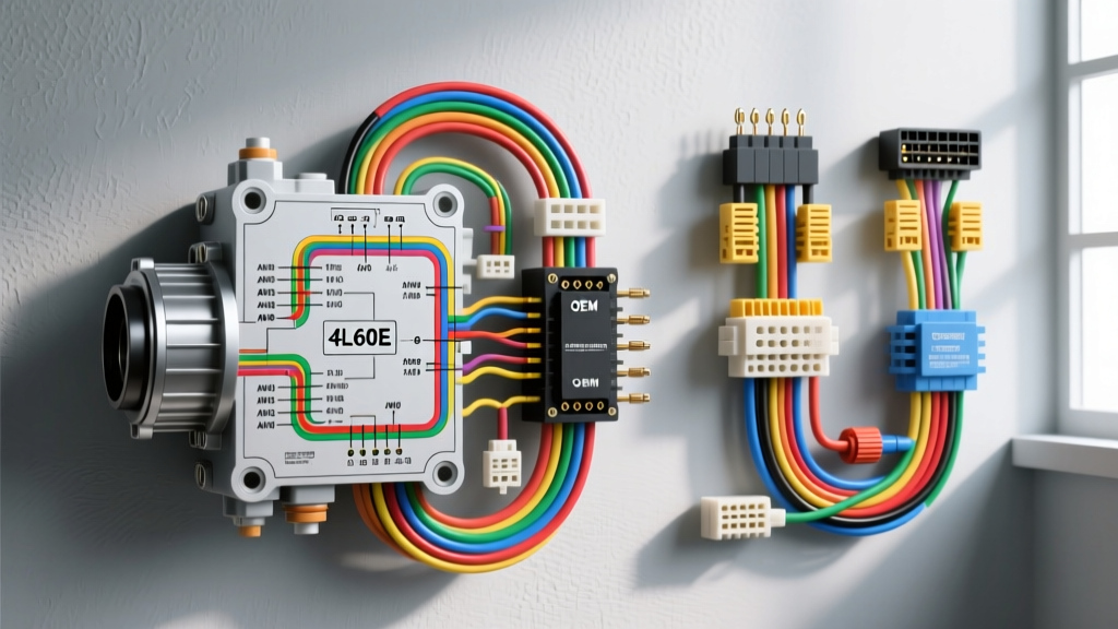
Decoding the GM 4L60E Transmission Wiring Diagram
Swapping a GM 4L60E into a classic muscle car, hot rod, or custom off-road rig requires significantly more than just bolting it to the bellhousing. Because the 4L60E is an entirely electronically controlled transmission, improper wiring will immediately result in limp mode (defaulting to 3rd gear), harsh shifts, or complete torque converter clutch failure. Whether you are integrating it with a factory PCM or utilizing a standalone controller, understanding the core GM 4L60E transmission wiring diagram is mandatory for a successful build.
The transmission connects to the vehicle harness via a 13-pin circular Delphi bulkhead connector located on the passenger side of the transmission case. While it features 13 cavities, early to mid-production 4L60E units primarily utilize only 8 pins for solenoid control and sensor feedback. Below is the definitive pinout reference for the standard 4L60E internal case connector.
13-Pin Case Connector Pinout & Specifications
| Pin | Function | OEM Wire Color (Typical) | AWG | Signal Type |
|---|---|---|---|---|
| A | Shift Solenoid A (1-2 Shift) | Dark Blue | 18 AWG | 12V On/Off (Ground Switched) |
| B | Shift Solenoid B (2-3 Shift) | Yellow | 18 AWG | 12V On/Off (Ground Switched) |
| C | TCC PWM Solenoid | Light Green/Black | 18 AWG | PWM (Pulse Width Modulated) |
| D | 3-2 Downshift Solenoid | Brown/Black | 18 AWG | 12V On/Off (Ground Switched) |
| E | Pressure Control (PC) High Side | Light Blue/Black | 18 AWG | Variable Force (300 Hz PWM) |
| F | Pressure Control (PC) Low Side | Dark Green | 18 AWG | Variable Force Return |
| G | TFT Sensor Signal | Black | 20 AWG | Analog 5V Reference |
| H | TFT Sensor Ground | Yellow/Black | 20 AWG | Sensor Ground |
| J-N | Reserved / Unused (on early models) | N/A | N/A | N/A |
Harness Selection Guide: OEM vs. Aftermarket Solutions
When planning your swap, you must choose a wiring strategy. The market offers three primary "products" or pathways for wiring the 4L60E. Each has distinct advantages, costs, and technical requirements.
Option 1: Factory OEM PCM Integration
Using the factory Powertrain Control Module (PCM) from a donor vehicle (such as a 1998-2002 F-Body or 1999-2006 Silverado) is the most cost-effective route if you already possess the junkyard harness. However, the OEM harness is massive, heavily loomed, and packed with unnecessary emissions wiring.
- Pros: Lowest hardware cost; factory-grade shift algorithms; built-in torque management during shifts.
- Cons: Requires PCM reprogramming (HP Tuners) to disable VATS, rear O2 sensors, and emissions codes. The physical harness routing is complex and often requires depinning and re-routing through the firewall.
- Best For: Budget LS-swaps where the donor engine and transmission are kept as a matched set.
Option 2: Standalone Transmission Controllers (TCI EZ-TCU / Holley)
For those running a carbureted engine or an aftermarket EFI system without native transmission control, a standalone controller like the TCI EZ-TCU or Holley Terminator X is the premium choice. These systems use a simplified, dedicated harness that plugs directly into the 4L60E case connector.
- Pros: Drastically simplified wiring diagram; intuitive laptop/handheld tuning; no donor PCM required; allows custom shift points and firmness adjustments on the fly.
- Cons: High initial cost ($700 - $1,200+); requires sourcing external TPS (Throttle Position Sensor) and VSS (Vehicle Speed Sensor) inputs.
- Best For: Carbureted V8 swaps, restomods, and custom builds where factory PCM integration is impossible.
Option 3: Pre-Loomed Universal Swap Harnesses
Companies like Painel Performance and Summit Racing offer universal 4L60E swap harnesses. These are essentially simplified OEM harnesses that strip away the emissions clutter, providing only the necessary wires for the transmission solenoids, a check engine light, and a diagnostic ALDL connector.
- Pros: Clean, color-coded, and pre-fused; saves dozens of hours of harness stripping and soldering; designed specifically for engine-bay routing.
- Cons: Still requires a compatible PCM to function; does not solve the tuning/VATS issue.
- Best For: Clean-room engine bay builds using a standalone EFI system that features a built-in transmission controller (like the Holley Dominator).
Advanced Signal Routing & Conditioning Requirements
Wiring the solenoids is only half the battle. The 4L60E relies heavily on external sensor inputs to calculate shift timing and line pressure. Failing to properly condition these signals is the number one cause of swapped-transmission failure.
VSS (Vehicle Speed Sensor) Signal Conditioning
The 4L60E tailhousing utilizes a 40-pulse per revolution (PPR) sine-wave AC VSS. The PCM or standalone controller uses this signal to determine vehicle speed and calculate shift points. If you are swapping this transmission into a classic car with an older electronic speedometer, the speedometer will likely not read the 40-PPR sine wave correctly. You must install a VSS signal conditioner (such as the Dakota Digital SGI-5E) to convert the raw transmission signal into a clean, calibrated square wave that both your controller and dashboard can read simultaneously.
Flyback Diode Protection for Custom Controllers
If you are building a custom microcontroller harness or using basic automotive relays to test shift solenoids, you must understand inductive kickback. Shift Solenoids A and B are highly inductive loads. When the controller cuts the ground circuit to turn the solenoid off, the collapsing magnetic field generates a massive reverse voltage spike (often exceeding 100V). OEM PCMs feature internal clamping diodes to absorb this spike. If your custom controller lacks this protection, the spike will instantly fry your microcontroller's output drivers. Always install 1N4007 flyback diodes across the solenoid power and ground wires, with the diode stripe facing the 12V source, to safely recirculate the inductive energy.
Common Failure Modes & Routing Best Practices
Even with a perfect schematic, physical wire routing dictates the longevity of your 4L60E harness. According to SAE International wiring standards, automotive harnesses must be protected from extreme heat, abrasion, and fluid intrusion.
The Bellhousing Chafe Point
The most common physical failure of the 4L60E harness occurs where the wiring bundle crosses the bellhousing near the exhaust crossover or starter motor. The vibration of the powertrain will saw through standard corrugated loom and wire insulation within a few thousand miles, causing a short to ground. This usually blows the PCM's internal solenoid driver or the under-hood fuse block's IGN fuse. Fix: Always wrap the harness segment crossing the bellhousing in high-temp silicone fiberglass sleeving and secure it with adel clamps to the transmission pan bolts, keeping it at least 3 inches away from exhaust manifolds.
TFT Sensor Thermistor Drift
The Transmission Fluid Temperature (TFT) sensor is a Negative Temperature Coefficient (NTC) thermistor. As fluid heats up, resistance drops. At 77°F (25°C), resistance should be approximately 10,000 ohms. At 200°F (93°C), it drops to roughly 1,100 ohms. If the wiring harness develops micro-fractures or corrosion at Pin G or Pin H, the PCM will read an artificially high resistance, interpreting it as sub-zero fluid temperatures. This triggers the PCM's "cold shift schedule," resulting in harsh, delayed shifts and the disabling of the TCC lockup to prioritize fluid warmup. Always use dielectric grease on the 13-pin bulkhead connector and ensure the mating surfaces are free of ATF residue.
Summary
Mastering the GM 4L60E transmission wiring diagram is the bridge between a frustrating project car and a reliable, high-performance machine. By selecting the correct harness architecture for your specific EFI setup, respecting the AWG requirements of the PWM solenoids, and properly conditioning your VSS signals, you ensure the transmission operates exactly as the engineers intended. For further integration specifications regarding modern EFI systems managing legacy transmissions, consult the Holley Terminator X technical documentation or your specific PCM tuning software provider.