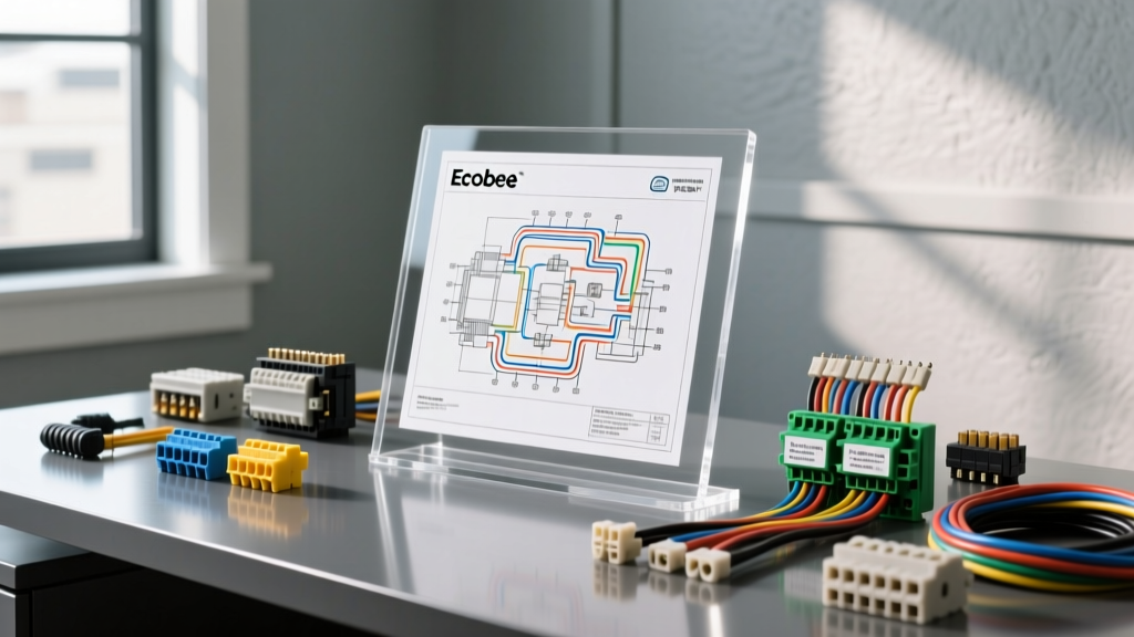
The Search for the Ecobee PEK Wiring Diagram PDF in Automotive Applications
When customizing Class A motorhomes, expedition trucks, or heavy-duty sleeper cabs, builders frequently search for an ecobee pek wiring diagram pdf to integrate smart climate control. The appeal of the Ecobee smart thermostat is undeniable: remote monitoring, automated scheduling, and precise temperature management. However, applying residential HVAC schematics to vehicle platforms introduces severe electrical hazards. The Power Extender Kit (PEK) is designed to multiplex 24VAC signals over existing wires when a dedicated C-wire (Common) is absent. In a residential home, this is a straightforward workaround. In a vehicle, it is a complex engineering challenge.
Most recreational vehicles and commercial trucks utilize 12VDC or 24VDC control boards for their Dometic, Furrion, or Coleman Mach air conditioning units. The standard Ecobee PEK wiring diagram PDF explicitly assumes a 24VAC alternating current environment. Attempting to wire a PEK module directly into a 12VDC vehicle harness will instantly destroy the multiplexer board, and worse, backfeed DC voltage into your smart thermostat, causing catastrophic failure. This guide provides a comprehensive cost and tool requirements analysis for safely adapting smart thermostat technology to vehicle HVAC systems using isolated inverters and proper automotive wiring standards.
Voltage Architecture: Why the Standard PDF Fails in Vehicles
To successfully deploy an Ecobee and its PEK in a motorhome or truck sleeper, you must fundamentally alter the vehicle’s HVAC control architecture. Because running a new 18 AWG C-wire through the sealed, insulated walls of an RV or the structural bulkhead of a truck sleeper is often impossible, the PEK’s multiplexing capability is highly desirable. However, you must first install an isolated 12VDC to 24VAC HVAC inverter. The PEK must be wired exclusively on the load side of this inverter, treating the vehicle’s newly created 24VAC micro-grid exactly like a residential furnace control board.
According to the RV Industry Association (RVIA) guidelines on low-voltage and AC conversion systems, any DC-to-AC inverter used for sensitive control electronics must feature galvanic isolation to prevent chassis ground loops. If the inverter is not isolated, the vehicle’s 12VDC negative chassis ground will conflict with the PEK’s 24VAC common reference, leading to erratic Wi-Fi disconnects and blown fuses.
Tool Requirements for Automotive Smart Thermostat Retrofits
Executing a vehicle-specific smart thermostat retrofit requires precision tools designed for marine and automotive environments. Standard residential wire strippers will fray the fine strands of automotive-grade wire, leading to high-resistance connections that disrupt the PEK’s sensitive multiplexed data signals.
Essential Wiring & Crimping Tools
- True-RMS Multimeter: A high-quality meter like the Fluke 87V is mandatory. You must verify both the 12VDC input from the vehicle battery bank and the precise 24VAC RMS output of the isolated inverter before connecting the PEK.
- Automotive Wire Strippers: Calibrated for 18 to 22 AWG stranded wire. Do not use residential solid-core strippers.
- Ratchet Crimpers: Required for Molex KK 254 and RJ11/RJ12 modular connectors. A proper ratchet crimp ensures the gas-tight seal necessary to withstand vehicle vibration and thermal cycling.
- Marine-Grade Heat Shrink: Adhesive-lined, dual-wall heat shrink is required for all inline splices to prevent corrosion from the high-humidity environment inherent in RVs and truck cabs.
Wire Selection and SAE Standards
Never use standard residential 18 AWG solid copper thermostat wire in a vehicle. Vehicle vibration will cause solid core wire to work-harden, snap, and short out against the chassis. You must use SAE J378 or UL 1426 compliant marine-grade, tinned, stranded copper wire. For runs under 10 feet, 18 AWG is sufficient. However, in large Class A motorhomes where the HVAC control board is located in the rear bay and the thermostat is in the front living area, the wire run can exceed 25 feet. In these cases, you must upgrade to 16 AWG to prevent voltage drop on the multiplexed PEK signal, which can cause the Ecobee to misinterpret HVAC staging commands.
Cost Analysis: Components and Materials
Upgrading a vehicle HVAC system to support an Ecobee with a PEK is significantly more expensive than a residential installation due to the requirement for isolated power conversion and automotive-grade materials. Below is a realistic cost breakdown for a professional-grade expedition truck or motorhome retrofit.
| Component | Specification | Estimated Cost |
|---|---|---|
| Ecobee Smart Thermostat + PEK | Includes Power Extender Kit | $249.00 |
| Isolated DC-AC HVAC Inverter | 12VDC to 24VAC, 40VA, Galvanic Isolation | $115.00 |
| Marine Tinned Wire (16 AWG) | 5-conductor, 50ft spool, UL 1426 | $65.00 |
| Automotive Relay & Fuse Block | Waterproof, 5A mini-fuses, Deutsch connectors | $45.00 |
| Connectors & Terminals | Molex, RJ11, Heat Shrink, Crimps | $30.00 |
| Total Estimated Cost | Excluding Labor | $504.00 |
Vehicle-Specific Wiring Pinouts and Color Codes
When adapting the standard ecobee pek wiring diagram pdf to a vehicle, you are essentially bypassing the vehicle’s native 12V DC thermostat harness and wiring the PEK to the 24VAC side of your newly installed isolated inverter, which then triggers heavy-duty automotive relays to control the 12V DC roof units. Below is the mapping for a typical 5-wire setup utilizing the PEK module.
| PEK Terminal | Wire Color (16 AWG Marine) | Function / Destination | Voltage State |
|---|---|---|---|
| R | Red | 24VAC Hot from Isolated Inverter | 24VAC Constant |
| C | Black | 24VAC Common from Isolated Inverter | 24VAC Reference |
| Y1 | Yellow | Cooling Stage 1 Relay Coil | 24VAC Switched |
| W1 | White | Heating Stage 1 Relay Coil | 24VAC Switched |
| G | Green | Blower Fan Relay Coil | 24VAC Switched |
Note: The PEK module itself will intercept the R, C, Y1, W1, and G wires at the control board (inverter) location, multiplexing the signals so that only four wires need to run through the vehicle’s walls to the Ecobee wall plate.
Common Failure Modes & Troubleshooting
Even with the correct tools and an isolated inverter, vehicle environments introduce unique failure modes that do not exist in residential homes.
1. Chassis Ground Loops
Symptom: The Ecobee constantly reboots or drops Wi-Fi when the vehicle’s engine alternator is running.
Cause: The 24VAC inverter’s common terminal is bleeding into the vehicle’s 12VDC chassis ground due to improper isolation or a pinched wire rubbing against the steel frame.
Fix: Disconnect the C-wire from the chassis. Use the Fluke 87V to measure AC millivolts between the PEK’s C terminal and the vehicle chassis. Any reading above 50mV indicates a ground loop requiring better inverter isolation.
2. Voltage Drop on Multiplexed Signal
Symptom: The thermostat display works, but HVAC commands (cooling/heating) are delayed or fail to trigger the roof units.
Cause: Using 18 AWG wire on a 30-foot run in a motorhome causes a voltage drop. The PEK’s multiplexed data signal degrades below the threshold required for the wall plate to decode the staging commands.
Fix: Replace the 18 AWG run with 16 AWG marine tinned wire, or install a secondary 24VAC transformer near the thermostat to provide a dedicated, non-multiplexed C-wire, bypassing the PEK entirely.
3. Alternator Whine Interference
Symptom: The smart thermostat registers false temperature spikes or erratic humidity readings.
Cause: High-frequency AC ripple from the vehicle’s alternator is passing through a low-quality DC-AC inverter, introducing noise into the PEK’s data line.
Fix: Install a 1000µF electrolytic capacitor across the 12VDC input terminals of the inverter to smooth the DC ripple, and ensure all 24VAC wiring is routed at least 6 inches away from the vehicle’s main battery cables and alternator harness.
Conclusion
Searching for an ecobee pek wiring diagram pdf is the first step in a complex vehicle integration project. While the PEK is an ingenious solution for missing C-wires, its strict reliance on 24VAC power means it cannot be wired directly to any 12VDC automotive or RV HVAC system. By budgeting for an isolated inverter, utilizing SAE-compliant marine tinned wire, and employing proper ratcheting crimp tools, custom builders can successfully bring smart climate control to the most rugged expedition vehicles and luxury motorhomes on the road.