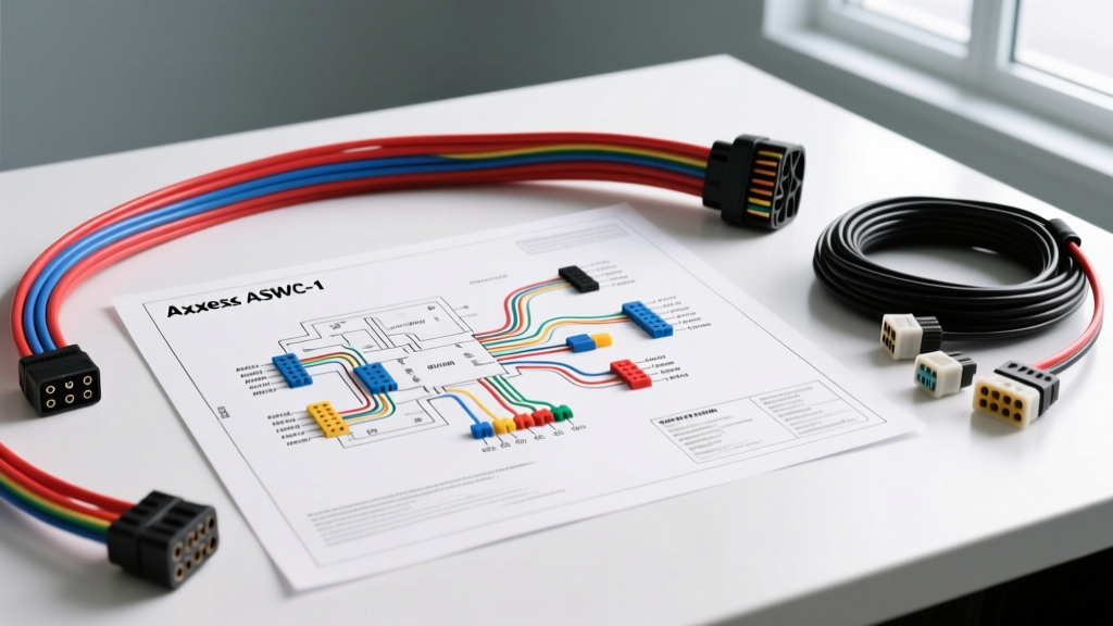
Introduction to the ASWC-1 Architecture
Integrating aftermarket head units with factory steering wheel controls requires bridging complex OEM multiplexed networks with standardized aftermarket resistive inputs. While many technicians search for a generic axxess aswc 1 wiring diagram pdf, the reality of modern automotive electrical systems demands a deeper understanding of network topologies. The Axxess ASWC-1 (Steering Wheel Control Interface) acts as a universal translator, intercepting OEM CAN-bus, GMLAN, or resistive ladder signals from the vehicle's clock spring and converting them into discrete analog resistance values that aftermarket radios (Alpine, Pioneer, Kenwood, Sony) can interpret.
This technical specification reference bypasses basic installation manuals to provide automotive electricians and integration specialists with exact pinout configurations, AWG splicing requirements, and OEM diagnostic matrices necessary for flawless SWC integration.
Axxess ASWC-1 Universal Harness Pinout Specification
The ASWC-1 utilizes a proprietary universal pigtail that must be spliced into the vehicle's specific SWC data circuits. Unlike standard 12V power harnesses, the data lines require precise routing to avoid electromagnetic interference (EMI) from high-current accessory circuits.
| Wire Color | Function | AWG | Technical Notes & Vehicle Application |
|---|---|---|---|
| Red | +12V Ignition (Switched) | 18 AWG | Must be sourced from a true ignition-controlled circuit. Do not use CAN-bus wake-up signals for primary power. |
| Black | Chassis Ground | 18 AWG | Must be terminated to a clean, unpainted chassis ground within 12 inches. Avoid daisy-chaining with high-draw amplifiers. |
| Green | SWC Data 1 / CAN-High | 20 AWG | Connects to OEM SWC Signal wire (Resistive) or CAN-High (Multiplexed). Verify via OEM wiring schematic. |
| Gray | SWC Data 2 / CAN-Low | 20 AWG | Connects to OEM SWC Return (Resistive) or CAN-Low. Left unconnected on single-wire GMLAN or simple resistive systems. |
Radio Patch Cable Pin Configurations
The ASWC-1 outputs translated analog resistance via a 3.5mm or 2.5mm TRS (Tip-Ring-Sleeve) connector. Understanding the pinout of these patch cables is critical when fabricating custom harnesses for rare or boutique head units.
- 3.5mm to 3.5mm (Alpine, Kenwood, Sony): Tip = SWC 1 (Data), Ring = SWC 2 (Return), Sleeve = Ground.
- 3.5mm to 2.5mm (Pioneer): Tip = SWC 1, Ring = SWC 2. Note that Pioneer radios often utilize a proprietary multi-pin connector; the 2.5mm jack is strictly for the SWC data lines, while the sleeve acts as the common shield.
OEM Steering Wheel Control Network Topologies
To properly utilize the ASWC-1 wiring diagram, you must first identify the OEM network architecture. The interface auto-detects the protocol, but the physical wiring connection varies drastically between topologies.
1. Resistive Ladder Networks
Common in older Ford, Nissan, and Chrysler vehicles. The OEM clock spring contains a series of resistors wired in parallel. Pressing a button routes current through a specific resistor, altering the total resistance on the circuit. The ASWC-1 reads this voltage drop across its internal pull-up resistor network. Only the Green (Signal) and Gray (Return) wires are used.
2. High-Speed CAN-Bus (Dual Wire)
Found in modern VW, Audi, and late-model Ford platforms. The steering wheel module (SWM) digitizes button presses and broadcasts them via CAN-High and CAN-Low. The ASWC-1 Green and Gray wires must be spliced directly into the CAN-H and CAN-L lines originating from the clock spring. Proper twisted-pair maintenance is critical here to preserve the SAE J1939 impedance requirements.
3. GMLAN (Single Wire CAN)
General Motors' proprietary single-wire network. The SWC data is multiplexed over a single wire (typically Green/White or Brown/White). The ASWC-1 Green wire taps this single line, while the Gray wire remains insulated and unused.
Clock Spring Tapping and Wire Gauge Requirements
The most common point of failure in SWC integration is poor splicing technique at the clock spring rotary coupler. OEM clock spring harnesses typically utilize 22 AWG to 24 AWG stranded copper to maintain flexibility within the steering column's rotational mechanism.
According to IPC/WHMA-A-620 standards for wiring harness assemblies, splicing a thicker 20 AWG ASWC-1 wire to a 24 AWG OEM wire using standard T-taps will result in cold joints and intermittent signal loss due to vibration. T-taps are strictly prohibited on CAN-bus networks due to the introduction of stub-line reflections.
Recommended Splicing Protocol:
- Strip 3/16" of insulation from both the OEM 24 AWG and ASWC 20 AWG wires.
- Use a MIL-SPEC solder sleeve with an integrated heat-shrink seal and pre-formatted solder ring.
- Apply heat at 200°C until the solder ring flows completely through the stranded wire matrix.
- This ensures a hermetic seal against steering column moisture and maintains the flexible bending radius required for column wiring.
Resistive Ladder Diagnostic Matrix
Before connecting the ASWC-1 to a resistive vehicle, verify the health of the OEM clock spring and button membrane using a Digital Multimeter (DMM). Back-probe the clock spring connector and measure resistance while actuating the buttons. Below is a standard Ford resistive matrix reference:
| Button Function | Expected OEM Resistance (±5%) | ASWC-1 Auto-Detect Behavior |
|---|---|---|
| Volume Up | 0 Ω (Dead Short) | Registers as baseline reference |
| Volume Down | 220 Ω | Translates to 3.5mm Tip resistance drop |
| Seek Up / Next | 470 Ω | Translates to secondary resistance tier |
| Seek Down / Prev | 1000 Ω (1 kΩ) | Translates to tertiary resistance tier |
| Mode / Source | 2200 Ω (2.2 kΩ) | Translates to quaternary resistance tier |
Note: If your DMM reads infinite resistance (OL) across all buttons, the internal clock spring ribbon cable has fractured—a common failure mode requiring mechanical replacement before the ASWC-1 can be installed.
Oscilloscope Diagnostics for CAN-Bus SWC Networks
When integrating the ASWC-1 into a CAN-bus SWC network, relying solely on a DMM is insufficient. A DMM will only show an average voltage (typically 2.5V on CAN-H and 2.5V on CAN-L at idle). To verify network integrity before splicing the ASWC-1 harness, use a dual-channel oscilloscope.
- CAN-High Idle: 2.5V
- CAN-Low Idle: 2.5V
- CAN-High Dominant: Spikes to ~3.5V
- CAN-Low Dominant: Drops to ~1.5V
If the dominant voltage differential (2.0V total) is not present when pressing steering wheel buttons, the OEM Steering Wheel Control Module is either asleep or lacking a ground. The ASWC-1 cannot generate missing CAN packets; it can only intercept and translate existing ones. Furthermore, verify the 60-ohm termination resistance across the CAN-H and CAN-L lines at the clock spring connector to ensure the network bus is properly terminated.
Advanced Troubleshooting Decision Tree
When the ASWC-1 fails to retain settings or auto-detect the vehicle network, follow this diagnostic sequence:
Symptom: ASWC-1 LED Flashes Continuously, Radio Does Not Respond
- Cause 1: Incorrect Radio Patch Cable. Verify if the head unit requires a 3.5mm or 2.5mm connection. Plugging a 3.5mm jack into a Pioneer 2.5mm port will short the SWC 1 and Ground pins.
- Cause 2: Head Unit SWC Setting Disabled. Many modern Kenwood and Alpine units require the user to manually enable 'Steering Wheel Control' or 'Wired Remote' in the hidden dealer settings menu before the 3.5mm port becomes active.
Symptom: ASWC-1 Auto-Detects Incorrect Protocol (e.g., Detects VW on a Ford)
- Cause: Parasitic voltage on the SWC Data line. If the vehicle's OEM radio is still connected to the CAN-bus during the ASWC-1 programming phase, the OEM radio's internal pull-up resistors can skew the ASWC-1's detection algorithm.
- Fix: Disconnect the OEM radio completely. Perform the ASWC-1 manual override programming sequence (holding the reset button during power-up) to force the correct vehicle protocol based on the official Metra/Axxess vehicle application guide.
Symptom: Intermittent Volume Spikes or Ghost Inputs
- Cause: Ground Loop or EMI Induction. The Gray (Return) wire has been grounded to the chassis instead of being routed back to the clock spring return pin, or the data wires are zip-tied to an aftermarket amplifier power cable.
- Fix: Ensure the Gray wire is connected only to the OEM SWC Return wire at the clock spring. Reroute the ASWC-1 harness away from high-current 12V power delivery systems.