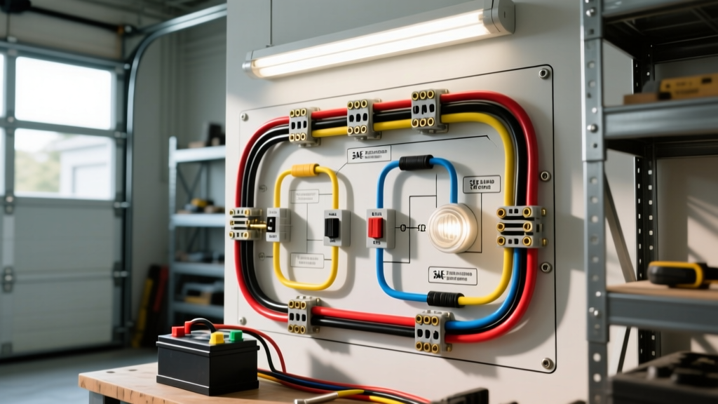
Advanced Topology of RV 12V Entry Lighting Systems
When automotive and RV electrical technicians consult a standard residential wiring diagram for porch light installations, they are looking at 120V AC circuits governed by the NEC. However, interpreting the wiring diagram for porch light systems on recreational vehicles, travel trailers, and fifth wheels requires a deep understanding of 12V DC architecture, SAE wire standards, and chassis grounding protocols. The RV entry porch light is a critical safety circuit, often integrated with awning lights, step-well illumination, and exterior security cameras. This advanced technical guide deconstructs the 12V DC porch light circuit, detailing discrete wiring topologies, modern multiplex CAN-bus integrations, and precise diagnostic procedures for voltage drop and PWM interference.
Legacy Discrete Wiring Diagram for Porch Light Circuits
In traditional RV electrical systems (pre-2015 models and many current travel trailers), the porch light operates on a dedicated discrete 12V DC circuit. The circuit originates at the 12V DC distribution panel (converter/fuse block), protected by a 5A or 10A ATO/ATC blade fuse. From the fuse block, a primary 14 AWG or 16 AWG feed wire routes to the interior entry door rocker switch, and subsequently to the exterior fixture.
SAE J1128 Wire Specifications & Color Codes
Unlike residential copper wiring, RV manufacturers utilize thin-wall, cross-linked polyethylene insulated wire to reduce weight and withstand high engine compartment or chassis temperatures. According to SAE J1128 standards, GXL or TXL wire is the industry standard for 12V DC lighting circuits.
| AWG Size | SAE Type | Insulation Thickness | Max Ampacity (12V DC) | Standard RV Color Code | Application |
|---|---|---|---|---|---|
| 14 AWG | GXL / TXL | 0.023 in (0.58 mm) | 15A | Black (Feed), Red (Switched) | Main Feed from Fuse Panel to Switch |
| 16 AWG | GXL / TXL | 0.023 in (0.58 mm) | 10A | Red (Load), White (Ground) | Switch to Porch Light Fixture |
| 18 AWG | GXL / TXL | 0.023 in (0.58 mm) | 7A | White (Ground) | Fixture to Chassis Ground / Bus Bar |
Component Pinouts: Carling Contura Rocker Switches
The most common failure point in the RV porch light circuit is the interior entry switch. Winnebago, Thor Industries, and Forest River predominantly use Carling V-Series or Contura illuminated SPST (Single Pole, Single Throw) rocker switches. Understanding the pinout is critical when diagnosing a dead porch light or retrofitting an illuminated switch.
- Pin 1 (Ground for Internal LED): Connects to the 12V DC negative bus. This illuminates the switch indicator when the main circuit is active.
- Pin 2 (Load / Output): Connects to the positive wire routing through the chassis wall to the exterior porch light fixture.
- Pin 3 (Source / Input): Connects to the 12V positive feed from the distribution panel's fused terminal.
Diagnostic Note: If the porch light works but the switch indicator LED fails to illuminate, check the continuity between Pin 1 and the DC negative bus bar. A corroded ground spade terminal at Pin 1 is a frequent culprit in high-humidity environments.
Modern Multiplex CAN-Bus Porch Light Integration
In late-model Class A and Class C motorhomes, physical wire runs from the switch to the light have been replaced by multiplex control systems (e.g., Spyder Controls, Intellitec, or Coachmen multiplex nodes). When reviewing the wiring diagram for porch light circuits in these advanced RVs, you will not find a direct 12V load wire passing through the entry switch.
Instead, the entry switch is a low-current momentary or toggle input device connected to a local multiplex node via a LIN-bus or CAN-bus communication wire (typically a twisted pair of 22 AWG shielded wires). When the switch is actuated, the node sends a digital command to the main power distribution module, which then closes a solid-state relay (SSR) or MOSFET to send 12V+ directly to the porch light fixture. Troubleshooting these systems requires an OEM diagnostic scan tool or a multiplex node breakout box to verify network communication, rather than a standard multimeter continuity test.
Grounding Protocols and Voltage Drop Calculations
Automotive and RV electrical experts know that 90% of 12V lighting failures are ground-side faults. While older travel trailers often grounded the porch light fixture directly to the aluminum exterior skin or steel chassis, this practice violates modern RVIA (Recreational Vehicle Industry Association) best practices due to galvanic corrosion and high-resistance joints.
Modern wiring diagrams mandate a dedicated 12V- (White) ground wire routed all the way back to the main DC negative bus bar or a localized, bonded ground terminal block. To verify circuit health, perform a voltage drop test under load:
- Turn on the porch light (ensure the LED fixture is drawing its nominal current, typically 0.2A to 0.5A).
- Set your multimeter to DC Volts.
- Place the red probe on the 12V+ terminal at the fuse block and the black probe on the 12V+ wire at the fixture. A reading above 0.2V indicates excessive resistance in the positive feed (corroded splices or undersized wire).
- Place the red probe on the fixture's ground terminal and the black probe on the main DC negative bus bar. A reading above 0.1V indicates a compromised ground path.
LED Retrofitting and PWM Interference Diagnostics
Upgrading incandescent RV porch lights to LED fixtures introduces new electrical anomalies. Because LEDs draw significantly less current, they are highly susceptible to phantom voltage and Pulse Width Modulation (PWM) interference generated by the RV's inverter/charger or solar MPPT charge controllers.
Symptom: Porch Light Glows Faintly When Switched Off
Cause: Capacitive coupling or leakage current from an illuminated switch or a solid-state multiplex relay. Even 10mA of leakage current is enough to excite the phosphors in a high-efficiency LED porch light array. Solution: Install a 10k-ohm, 1/2-watt ceramic bleed resistor in parallel across the load and ground terminals at the light fixture. This provides a path for the leakage current, bypassing the LED driver.
Symptom: Strobe Effect or Flickering When Engine is Running
Cause: The RV's alternator or a poorly filtered PWM solar charge controller is introducing high-frequency AC ripple into the 12V DC bus. The LED driver inside the porch light attempts to rectify this noisy signal, resulting in a visible strobe effect. Solution: Verify the AC ripple on the DC bus using an oscilloscope or a multimeter with an AC mV setting. If ripple exceeds 50mV AC, install an inline 12V DC power filter (LC filter) or a transient voltage suppression (TVS) diode array just upstream of the porch light fixture to clamp the voltage spikes.
Exterior Connector Weatherproofing Standards
The transition point where the wiring passes through the exterior fiberglass or aluminum skin to the porch light fixture is highly vulnerable to water ingress. Standard butt connectors will fail within two seasons due to capillary action drawing moisture into the wire strands. Professional RV technicians mandate the use of adhesive-lined marine heat shrink (dual-wall polyolefin) and dielectric grease. For high-end motorhome builds, the wiring diagram often specifies a Deutsch DT series 2-pin waterproof connector integrated into the harness behind the fixture, allowing for tool-free removal and guaranteed IP67 weather sealing during long-term storage or winterization.