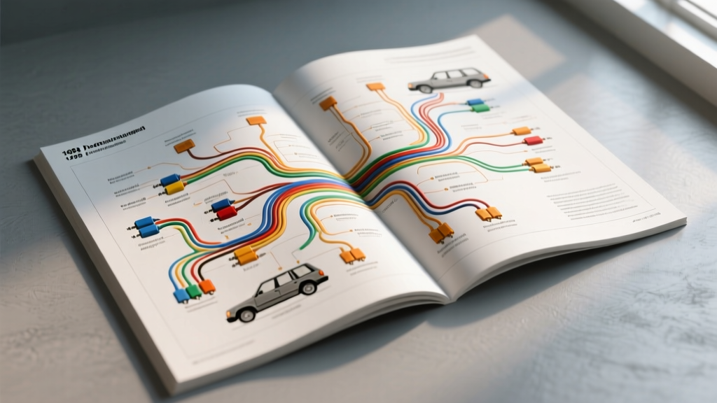
Understanding the 1998 Jeep Cherokee (XJ) Electrical Architecture
The 1998 Jeep Cherokee (XJ platform) represents a pivotal year in Chrysler's Jeep/Truck Engine Controller (JTEC) evolution. By 1998, the 4.0L inline-6 engine was fully OBD-II compliant, relying on a highly integrated Powertrain Control Module (PCM) to manage both engine and transmission functions. When utilizing a 1998 Jeep Cherokee wiring diagrams PDF, technicians must understand that the electrical system is divided into distinct power distribution centers (PDC), junction blocks (JB), and the infamous C101 bulkhead connector. Unlike earlier models, the 1998 XJ utilizes multiplexed-style ground routing and PCM-controlled alternator field circuits, making accurate schematic interpretation mandatory for successful diagnostics. According to ALLDATA OEM Repair Information, misinterpreting the splice pack locations or ground distribution trees in the factory diagrams is the leading cause of misdiagnosed 'ghost' electrical faults in the 1998 XJ.
Navigating Your 1998 Jeep Cherokee Wiring Diagrams PDF
Before initiating any troubleshooting flow, familiarize yourself with the nomenclature used in the factory Chrysler wiring schematics. The PDF diagrams utilize specific identifiers:
- C101: The 34-way bulkhead connector located on the driver's side firewall, bridging the engine bay harness to the interior dash harness.
- G104 / G106: Critical engine block ground locations. G104 is located at the rear of the cylinder head, while G106 is on the passenger side rear block.
- Splices (Sxxx): Indicated by solid black dots on the wiring diagram. These are often taped inside the main harness loom and are prime locations for moisture-induced corrosion.
- Wire Colors: Chrysler uses two-tone color codes. For example, 'DB/OR' translates to Dark Blue with an Orange tracer stripe.
Adhering to SAE J1128 Low Tension Primary Cable Standards, the wire gauges in your 1998 Cherokee range from 18 AWG for standard sensor signals down to 4 AWG or 8 AWG for main battery and engine ground straps. Always verify the AWG size noted in the diagram's legend before splicing or replacing damaged harness segments.
Troubleshooting Flow 1: Crank No-Start (CPS & ASD Relay)
The most common failure point on the 1998 4.0L XJ is a Crank-No-Start condition stemming from the Crankshaft Position Sensor (CPS) or the Automatic Shutdown (ASD) relay circuit. Use this step-by-step flow alongside your wiring diagram PDF to isolate the fault.
Step 1: Verify ASD Relay Engagement
- Locate the PDC (Power Distribution Center) under the hood. Identify the ASD Relay.
- Using a Digital Multimeter (DMM), check for 12V B+ at the relay's power feed terminal (Red wire, 10 AWG).
- Have an assistant crank the engine. The PCM grounds the ASD relay coil via a Dark Blue/Yellow (DB/YL) wire. If the relay does not click, verify continuity on the DB/YL wire to PCM Connector C2, Pin 51.
- Decision Node: If the relay clicks but there is no 12V output on the Dark Green/Orange (DG/OR) feed wire, check Splice S142 in the engine harness for an open circuit.
Step 2: Back-Probe the CPS Connector
If the ASD relay engages but the engine still fails to start, the PCM is likely not seeing a crank signal. The 1998 CPS is a 3-wire Hall-effect sensor located on the driver's side bellhousing.
- Disconnect the CPS connector and inspect for oil intrusion or bent pins.
- Reconnect and back-probe the harness side with your DMM set to DC Volts.
- Pin 1 (Orange): 5V Reference from PCM. If 0V, check for a short to ground in the Orange wire.
- Pin 2 (Gray/Black): Signal Return. During cranking, this should oscillate between 0V and 5V. A flat 5V or 0V indicates a dead sensor or a damaged flexplate notch.
- Pin 3 (Black/Light Blue): Sensor Ground. Must read less than 0.05V drop relative to the battery negative terminal.
Step 3: Inspect Ground G104
The PCM and CPS share ground paths routed through the cylinder head. If G104 (secured by a 10mm bolt at the rear of the head) is corroded, the CPS signal will float, causing the PCM to cut fuel injector pulse. Remove the bolt, clean the casting with a wire wheel, and reinstall using a star washer to ensure a solid chassis ground.
Troubleshooting Flow 2: Intermittent Stalling & Gauge Cluster Drops
If your 1998 Cherokee experiences sudden gauge cluster blackouts, ABS light illumination, and intermittent stalling while driving, the C101 Bulkhead Connector is your primary suspect. The Haynes Jeep Cherokee Repair Manual frequently highlights the C101 as a major failure point due to its low firewall placement, making it susceptible to water ingress and thermal cycling.
Step 1: Isolate the C101 Connector
- Locate the 34-way C101 connector on the driver's side firewall, just behind the brake booster.
- Disconnect the harness halves. Inspect the male and female terminals for green/white corrosion or 'fretting' (micro-abrasions on the contact surfaces).
- Check the Pink (PK) wire cavity. This is the main Fused B+ feed for the instrument cluster and PCM logic. A voltage drop here causes the dash to die while the engine runs, eventually stalling the engine when the PCM loses keep-alive memory.
Step 2: Bypass or Re-Pin the C101
If corrosion is found, simply cleaning it is a temporary fix. The professional standard is to either re-pin the affected cavities using Chrysler-specific weather-pack terminals or, for off-road dedicated vehicles, cut out the C101 and solder the wires directly, sealing them with marine-grade heat shrink. When referencing your 1998 Jeep Cherokee wiring diagrams PDF, map each pin carefully before cutting, as wire colors may fade or become discolored from engine bay heat.
Troubleshooting Flow 3: Charging System & PCM Field Control
Unlike older vehicles with internal voltage regulators, the 1998 XJ's alternator field is controlled directly by the PCM based on battery temperature sensor (BTS) data and system load. If you are seeing overcharging (15V+) or undercharging (11V) conditions, follow this flow.
Step 1: Verify Field Control Wires
- Locate the 2-pin connector on the rear of the alternator.
- Pin 1 (Dark Green/Light Blue - DG/LB): This is the field control circuit from the PCM. The PCM pulses this ground circuit (PWM) to control alternator output.
- Pin 2 (Dark Green/Orange - DG/OR): Fused B+ feed from the ASD relay circuit. Must have 12V with the key in the 'RUN' position.
Step 2: Test the Battery Temperature Sensor (BTS)
The BTS is located under the battery tray. If the BTS fails and reports freezing temperatures to the PCM, the PCM will command maximum alternator output, potentially boiling the battery. Use your DMM to measure the resistance of the BTS. At 70°F (21°C), the resistance should be approximately 9,000 to 11,000 ohms. If it reads open or shorted, replace the sensor and clear the PCM codes.
1998 Jeep Cherokee PCM Pinout Reference Table
When using your wiring diagrams PDF to diagnose PCM-level faults, reference this partial pinout for the 1998 4.0L JTEC Controller (Connector C1 - 32 Way Black Connector):
| PCM Pin | Wire Color | Circuit Function | Specification / Expected Value |
|---|---|---|---|
| 4 | BK/LB | Sensor Ground (CPS/TPS/MAP) | < 0.05V Drop to Battery Neg |
| 6 | OR | 5V Reference Supply | 4.8V - 5.2V (Key On) |
| 24 | GY/BK | Crankshaft Position Signal | 0V - 5V Square Wave (Cranking) |
| 30 | VT/BK | Ignition Coil Driver (-) | 12V (Dwell), 0V (Firing) |
| 32 | RD | Fused B+ (Battery Feed) | 12.6V (Constant) |
Essential Diagnostic Tools & SAE Standards
To properly execute these troubleshooting flows, a standard test light is insufficient and can damage the 1998 JTEC PCM's internal drivers. You must use a high-impedance Digital Multimeter (DMM) with a minimum 10-megohm input impedance. For alternator field and CPS signal diagnostics, a graphing multimeter or automotive oscilloscope is highly recommended to visualize the PWM duty cycle and square wave patterns.
When repairing wiring, always adhere to SAE J1128 standards for primary cable selection. Use Cross-Linked Polyethylene (XLPE) insulated wire (TXL or GXL types) which withstands the high under-hood temperatures of the 4.0L engine bay far better than standard PVC wire. For main ground strap replacements, utilize 8 AWG or 4 AWG oxygen-free copper with closed-end ring terminals, crimped with a hex-crimp tool and sealed with adhesive-lined heat shrink to prevent the XJ's notorious galvanic corrosion.
Conclusion
Successfully diagnosing the 1998 Jeep Cherokee requires moving beyond simple part-swapping and adopting a systematic, schematic-driven approach. By keeping a high-quality 1998 Jeep Cherokee wiring diagrams PDF on hand and following these structured troubleshooting flows, you can accurately pinpoint faults in the CPS circuit, C101 bulkhead connector, and PCM-controlled charging system. Proper interpretation of wire colors, splice locations, and AWG requirements will ensure your XJ remains reliable on the street and the trail.