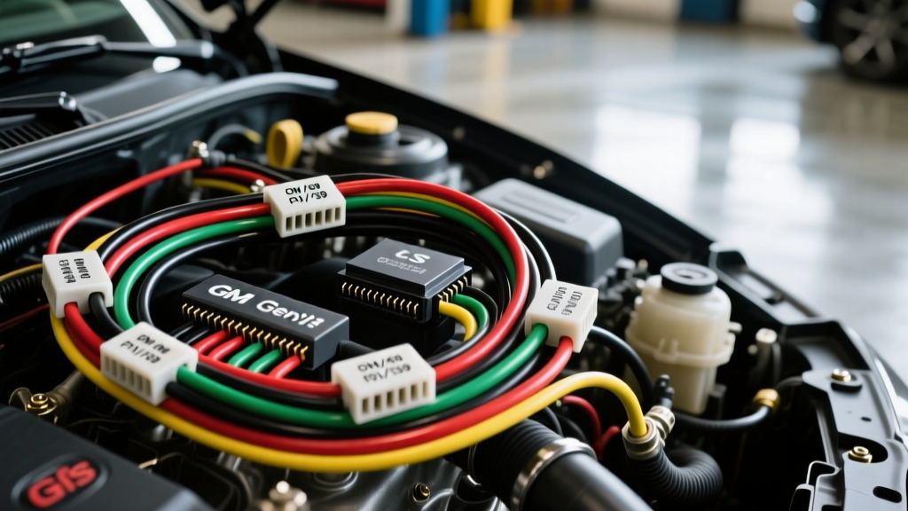
Introduction to Gen III/IV LS Harness Architecture
When executing a modern engine swap into a classic chassis, interpreting the car wiring harness diagram is the most critical phase of the build. The GM Gen III and Gen IV LS platforms (LS1, LS6, LS2, LS3) are the gold standard for aftermarket swaps, but their electrical complexity requires a fundamental understanding of OEM topology. Unlike older carbureted or early TBI setups, the LS engine harness relies on a high-speed multiplexed data bus, shielded twisted-pair sensor circuits, and low-side saturated switch drivers.
This advanced technical deep dive focuses on the ubiquitous Gen III P01 and P59 Powertrain Control Modules (PCMs). We will bypass the basic chassis-side connections and dissect the core engine harness architecture, providing the exact pinouts, wire color codes, and AWG specifications required to build, modify, or troubleshoot a standalone LS harness.
PCM Connector Layout: The 80-Way Metri-Pack Architecture
The Gen III PCM utilizes two 80-pin connectors, manufactured by Delphi (now Aptiv) using the Metri-Pack 280 series terminal system. These connectors are sealed and feature secondary terminal position assurance (TPA) locks to prevent wire back-out in high-vibration environments.
- Connector C1 (Black): Handles main power feeds, chassis grounds, Class 2 Serial Data, and high-current outputs (fuel pump relay, cooling fans).
- Connector C2 (Red): Dedicated to engine sensors (5V references, low references, signal returns) and low-side injector/ignition coil drivers.
Understanding the separation of these circuits is vital. C2 contains highly sensitive analog-to-digital (A/D) converter inputs. Splicing C2 sensor wires with improper solder joints or unshielded wire will introduce electromagnetic interference (EMI), resulting in erratic fuel trims or misfire codes.
Essential P01/P59 PCM Pinout Matrix
Below is a reference table for the most critical circuits required to achieve a standalone 'run' condition. This data is extracted from OEM GM service documentation and cross-referenced with aftermarket standalone harness specifications.
| Connector | Pin | OEM Wire Color | AWG | Circuit Function |
|---|---|---|---|---|
| C1 (Black) | 1 | Pink | 16 | Ignition 12V (Run/Start) |
| C1 (Black) | 20 | Orange | 14 | Constant Battery 12V (Keep-Alive) |
| C1 (Black) | 40, 41 | Black/White | 14 | PCM Power Ground (Engine Block) |
| C1 (Black) | 59 | Purple | 20 | Class 2 Serial Data Bus |
| C2 (Red) | 12 | Yellow | 20 | MAF Sensor Signal |
| C2 (Red) | 13 | Black/White | 20 | MAF Low Reference (Sensor Ground) |
| C2 (Red) | 17, 18 | Dark Blue / Light Blue | 20 (Shielded) | CKP High / CKP Low (Twisted Pair) |
| C2 (Red) | 31 | Gray | 20 | 5V Reference A (TPS, MAP) |
Wire Gauge Specifications and SAE Standards
When modifying a car wiring harness diagram for a custom application, adhering to SAE J1128 standards for low-tension primary cable is non-negotiable. The OEM harness uses specific cross-linked polyethylene (XLPE) insulated wires, typically GXL or TXL, which offer high heat resistance and thin walls for tight packaging.
Current Carrying Capacity vs. Voltage Drop
A common mistake in aftermarket swaps is sizing wires based solely on amperage. For example, the fuel pump relay coil draws less than 2 amps, which technically allows for 20 AWG wire. However, the PCM triggers the relay via a low-side driver, and the relay must switch a high-current fuel pump. To prevent voltage drop across the chassis-to-engine gap, the PCM Pin 20 (Orange) and fuel pump relay feed circuits must utilize 14 AWG or 12 AWG wire. A 2-volt drop on a 12V fuel pump circuit can reduce pump speed by 15%, causing lean conditions under wide-open throttle (WOT).
Sensor Topologies: 5V Reference and Low Reference
The Gen III PCM utilizes a ratiometric 5V reference system for sensors like the Throttle Position Sensor (TPS) and Manifold Absolute Pressure (MAP). Pin 31 on C2 (Gray wire) supplies this 5V reference. If this circuit is shorted to ground, or if an aftermarket sensor draws too much current, the PCM will set a P0120/P0105 code and default to limp-home mode.
Equally critical is the Low Reference circuit (Black/White wires). This is not a chassis ground. It is a dedicated, isolated ground plane inside the PCM used for analog sensor returns. Tying a sensor's Low Reference wire to the engine block or chassis will introduce alternator whine and ground-loop noise into the A/D converter, causing erratic idle and false knock sensor readings.
Shielding and Twisted Pairs: The CKP/CMP Imperative
The Crankshaft Position (CKP) and Camshaft Position (CMP) sensors are variable reluctance (VR) or Hall-effect sensors operating in a high-EMI environment. According to HP Tuners VCM Suite documentation, the CKP signal (Pins 17 and 18 on C2) must be routed as a shielded twisted pair.
- Twist Rate: Minimum of 4 to 6 twists per foot to cancel out common-mode noise from the ignition coils and alternator.
- Shielding: The braided copper shield must be grounded at the PCM end only (Pin 19, Light Green/Black). Grounding both ends creates a ground loop, turning the shield into an antenna that induces voltage spikes, leading to crank-but-no-start conditions.
Advanced Troubleshooting Decision Tree
When diagnosing a standalone LS swap that cranks but fails to start, use the following harness-specific decision tree before condemning the PCM or fuel system.
- Symptom: Cranks, No Start, No Injector Pulse
- Check 1: Verify 12V at the Pink wire (Pin 1, C1) during the 'Start' position. If missing, the ignition switch is not triggering the PCM wake-up.
- Check 2: Check for VATS (Vehicle Anti-Theft System) interference. If the Class 2 Serial Data bus (Pin 59, C1) is not receiving a valid BCM security password, the PCM disables injectors. Fix: Use HP Tuners to disable VATS in the operating system.
- Symptom: Starts, Runs Rough, Random Misfire Codes (P0300)
- Check 1: Inspect the CKP sensor harness. Is the shield grounded at the sensor pigtail? Fix: Cut the shield drain wire at the sensor side; it must only ground at the PCM.
- Check 2: Measure voltage drop on the PCM ground circuits (Pins 40/41, C1) with the engine running. A drop greater than 0.1V indicates a corroded engine-to-chassis ground strap, causing the coil dwell times to fluctuate.
- Symptom: MAF Code (P0101/P0102) at High RPM
- Check 1: Verify the MAF Low Reference (Pin 13, C2) is not spliced into a chassis ground. Fix: Run a dedicated 20 AWG Black/White wire directly from the MAF sensor to Pin 13.
Splicing and Connector Best Practices
When extending or modifying the harness based on your car wiring harness diagram, avoid soldering in high-flex zones. Solder wicks into the wire strands, creating a rigid point that will eventually fatigue and break under engine vibration. Instead, use Raychem RT-1145 or similar solder-sleeve shield terminators for shielded wires, and utilize open-barrel crimps (specifically designed for Metri-Pack terminals) with a ratcheting crimp tool. For environmental sealing, apply dielectric grease to the connector cavities and use heat-shrink tubing with adhesive lining (dual-wall) over all inline splices.
For comprehensive aftermarket harness schematics and physical routing guides, refer to the Painless Performance technical manuals, which provide excellent visual references for standalone LS swap wiring topologies.
Conclusion
Mastering the GM LS car wiring harness diagram requires looking beyond simple point-to-point connections. It demands an understanding of signal isolation, voltage drop mitigation, and EMI shielding. By adhering to OEM wire color codes, respecting the Metri-Pack terminal standards, and properly configuring the Class 2 data bus and sensor low references, you can build a standalone harness that rivals factory reliability and performance.