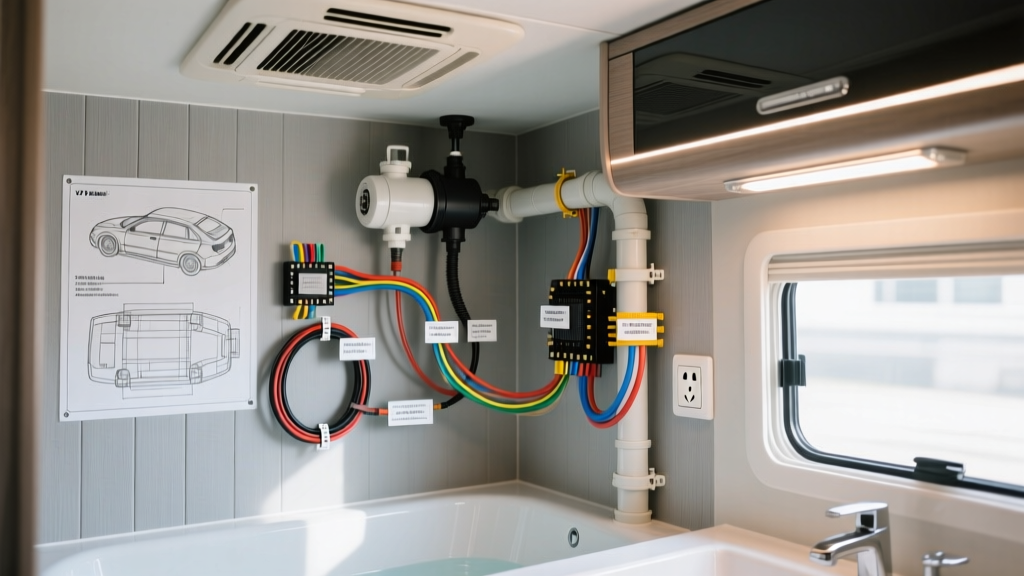
Introduction to RV Wet Bath Electrical Systems
Wiring a wet bath in a Class B camper van, Class C motorhome, or overland expedition trailer requires strict adherence to both automotive vibration standards and marine-grade moisture mitigation. Searching for a standard residential wiring diagram for a bathroom will lead to catastrophic failures in an RV environment due to chassis flex, 12V DC voltage drop, and high-humidity condensation. Unlike residential AC systems, vehicle bathrooms rely on a hybrid 12V DC and 120V AC architecture that must be isolated, properly fused, and protected against water ingress.
This product comparison and selection guide breaks down the best 12V components for RV bathrooms and provides a comprehensive schematic approach to wiring them safely according to RVIA NFPA 1192 Standards and ABYC E-11 guidelines.
Product Comparison: Selecting 12V Bathroom Components
Before laying out your wiring harness, you must select components that match your electrical system's capacity. High-amperage draws in a small wet bath can cause severe voltage drop if wire gauges are miscalculated.
12V Exhaust Fans: MaxxAir vs. Fan-Tastic Vent
- MaxxAir MaxxFan Deluxe (07500K): Features a 10-speed motor and integrated rain shield. It draws a maximum of 3.8A at 12V DC. Its integrated control board requires a clean, regulated 12V source; voltage spikes from an unfiltered inverter/charger can fry the PCB. Requires 14 AWG wire.
- Fan-Tastic Vent 3350: Draws up to 4.0A. It uses a simpler analog thermostat and motor setup, making it slightly more forgiving of dirty DC power from older alternators, but it lacks the rain-safety auto-close feature of the MaxxAir.
12V Demand Water Pumps: Shurflo vs. Flojet
- Shurflo 4008 Revolution (3.0 GPM): The industry standard. Draws 6.0A under load. It features an internal thermal breaker, but the SAE J1128 wiring standard still mandates an external 10A ATO fuse at the distribution panel. Pin 1 is +12V, Pin 2 is Ground.
- Flojet Quiet Quad II: Draws 5.5A but utilizes a 4-chamber diaphragm design that reduces acoustic vibration. Requires 12 AWG wire due to longer typical wire runs to minimize voltage drop below 3%.
Comprehensive Wiring Diagram For A Bathroom in Motorhomes
A proper wiring diagram for a bathroom in a vehicle separates high-draw appliances from sensitive lighting circuits to prevent flickering when the water pump engages. Below is the circuit breakdown for a standard RV wet bath.
Circuit 1: Exhaust Fan and Vanity Lighting
The exhaust fan and LED vanity mirror should be wired on a shared 15A branch circuit from a Blue Sea Systems ST Blade fuse block.
Wire Routing: 14 AWG SAE J1128 GXL (Yellow for +12V, White for -12V).
Switching: Use an IP67-rated marine rocker switch with an LED indicator. The LED indicator must be wired in parallel with the load, not in series, to prevent voltage drop to the fan motor.
Circuit 2: Demand Water Pump and Accumulator Tank
The water pump requires a dedicated 10A or 15A circuit.
Wire Routing: 12 AWG GXL wire.
Crucial RVIA Code Note: Never use the vehicle chassis as a ground return for the water pump. The high moisture environment of a wet bath will cause galvanic corrosion on the chassis ground point, leading to pump failure and stray DC current in the plumbing. Always run a dedicated 12 AWG White negative wire back to the main DC negative busbar.
Circuit 3: 120V AC Heated Floors (Inverter Integration)
If your motorhome bathroom features 120V AC heated floor mats or a heated towel rack, this must be wired through a Pure Sine Wave Inverter (e.g., Victron MultiPlus).
Wire Routing: 12 AWG THHN stranded wire (Black for Hot, White for Neutral, Green for Ground).
Safety Requirement: NFPA 1192 strictly requires a GFCI (Ground Fault Circuit Interrupter) receptacle or breaker for any 120V AC circuit routed within 6 feet of an RV bathroom sink or shower pan.
RVIA & ABYC Wire Color Codes and AWG Specifications
Adhering to standardized color codes prevents fatal errors during future troubleshooting. The table below outlines the specifications for a standard vehicle wet bath wiring diagram.
| Component | System | AWG Size | Fuse/Breaker | Positive Wire Color | Negative/Neutral Color | Connector Type |
|---|---|---|---|---|---|---|
| 12V Exhaust Fan | 12V DC | 14 AWG | 10A ATO | Yellow | White | IP67 Deutsch DT |
| LED Vanity Mirror | 12V DC | 16 AWG | 5A ATO | Yellow | White | Adhesive Heat Shrink |
| Water Pump | 12V DC | 12 AWG | 15A ATO | Yellow | White | Spade w/ Insulator |
| Heated Floor Mat | 120V AC | 12 AWG | 15A GFCI | Black | White (Green GND) | Wire Nuts / Wago |
Routing, Connectors, and Moisture Mitigation
The environment inside a camper van or motorhome bathroom is hostile to electrical connections. Condensation from hot showers creates a 100% humidity environment that will oxidize standard automotive crimp connectors within months.
- Adhesive-Lined Heat Shrink: Every splice in the wet bath must use 3M adhesive-lined marine heat shrink. When heated, the inner epoxy melts and seals the wire strands, preventing capillary action from drawing moisture into the copper.
- Drip Loops: When wiring the ceiling exhaust fan or vanity lights, always create a "drip loop" before the wire enters the connector or switch housing. This ensures that any condensation running down the wire jacket drips off the bottom of the loop rather than flowing directly into the electrical terminal.
- Sealed Connectors: Replace standard Molex or spade connectors on the exhaust fan with IP67-rated Deutsch DT or Superseal 1.5 series connectors. These feature silicone secondary locks and ribbed seals that expand when mated, creating a watertight barrier.
Troubleshooting Common RV Bathroom Electrical Faults
When your bathroom electrical system fails, use this decision tree to isolate the fault based on real-world RV failure modes.
Symptom: Water Pump Short-Cycles When No Faucets Are Open
- Electrical Check: Use a multimeter to verify 12.6V at the pump terminals under load. If voltage drops below 11V, the pump's internal pressure switch will chatter.
- Mechanical Check: If voltage is stable, the issue is not electrical. Check the accumulator tank pre-charge (should be 2 PSI below the pump's cut-in pressure) and inspect the pump's internal check valve for calcium scale or debris.
Symptom: Exhaust Fan Hums But Does Not Spin
- Cause: Moisture ingress has corroded the 2-pin connector, creating high resistance. The motor receives enough current to hum, but not enough amperage to overcome the magnetic detent of the stator.
- Fix: Cut off the corroded connector. Clean the wire ends, apply dielectric grease, and install a sealed Deutsch DT connector. Verify the fan's internal PCB has not suffered water damage by inspecting for white oxidation on the solder joints.
Symptom: Vanity LEDs Flicker When Water Pump Engages
- Cause: The lighting and pump are wired on the same branch circuit with undersized feeder wires from the main busbar, causing a system-wide voltage drop when the pump's startup surge hits.
- Fix: Separate the circuits at the DC distribution panel. Ensure the main feeder wire from the battery bank to the fuse block is at least 6 AWG or 4 AWG to handle cumulative amperage without dropping voltage below 12.2V.
By treating your vehicle's wet bath with the same electrical rigor as a marine vessel, you ensure long-term reliability, safety, and compliance with RV industry standards.