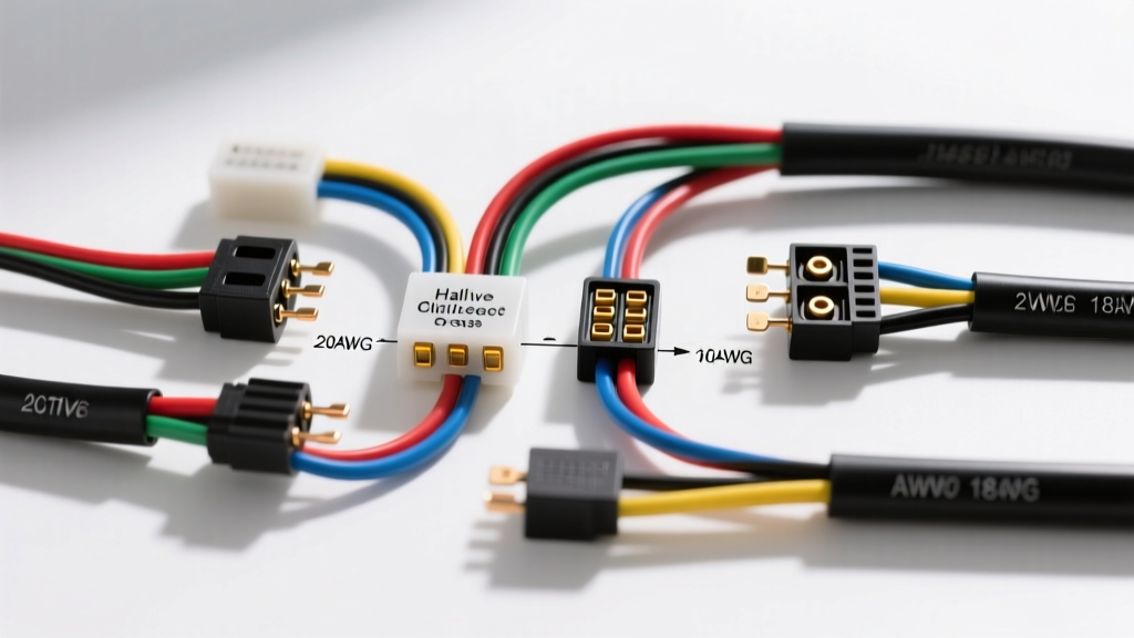
The Evolution of ABS Sensor Topologies
Understanding an ABS sensor wiring diagram requires first identifying the sensor topology. Anti-lock Braking Systems (ABS) have evolved significantly since their widespread adoption. Early systems relied on Variable Reluctance (VR) passive sensors, while modern Electronic Stability Control (ESC) and Advanced Driver Assistance Systems (ADAS) demand the zero-speed accuracy of active Hall-Effect or Anisotropic Magneto-Resistive (AMR) sensors. According to Bosch Mobility Solutions, the transition to active sensors was driven by the need for precise wheel speed data at sub-3 mph velocities, which is critical for hill-hold assist, electronic parking brakes, and autonomous emergency braking. Misidentifying the sensor type when reading a wiring schematic will lead to catastrophic diagnostic errors, as the voltage and current domains are entirely different.
Decoding the Passive (Variable Reluctance) ABS Sensor Wiring Diagram
Passive VR sensors are essentially inductive pickups consisting of a permanent magnet wrapped in a coil of fine copper wire. As the ferrous tone ring (reluctor ring) rotates past the sensor, the changing magnetic flux induces an Alternating Current (AC) sine wave. The frequency of this sine wave correlates directly to wheel speed, while the amplitude correlates to the speed and the air gap between the sensor tip and the tone ring.
Passive Wiring Specifications & Harness Architecture
- Wire Count: 2-wire configuration (Signal High, Signal Low).
- Wire Gauge: Typically 20 AWG to 22 AWG.
- Cable Architecture: Shielded Twisted Pair (STP). The twist rate is critical—OEMs mandate a minimum of one twist per inch to cancel out electromagnetic interference (EMI) from high-current ignition and alternator circuits.
- Shield Drain Wire: Must be grounded at the ABS control module harness connector ONLY. Grounding the shield at the sensor end creates a ground loop, introducing 60Hz alternator whine into the signal trace, which the ABS module interprets as erratic wheel slip.
- Air Gap Sensitivity: 0.020 to 0.050 inches. Output voltage ranges from 100mV AC at low speeds to over 2.0V AC at highway speeds.
Active (Hall-Effect & Magneto-Resistive) Wiring Schematics
Active sensors contain integrated circuitry (IC) within the sensor housing, requiring an external power supply from the ABS module. They output a digital square wave (PWM) or a current-modulated signal, providing absolute wheel speed and direction (forward/reverse) data down to 0 mph. Active sensors are categorized into two distinct wiring architectures: 2-wire current domain and 3-wire voltage domain.
2-Wire Active Sensors (Current Modulation)
In a 2-wire active system, the ABS module supplies a constant DC voltage (typically 5V to 12V) to the sensor. The sensor modulates the current draw on the circuit to communicate data. A standard protocol uses a baseline current of 7mA (low state) and pulses to 14mA (high state) as each tone ring tooth passes. Because the data is encoded in the current domain, this architecture is highly resistant to voltage drops caused by minor harness corrosion or long wire runs.
3-Wire Active Sensors (Voltage Domain / PWM)
Three-wire active sensors utilize a dedicated power, ground, and signal circuit. The ABS module provides a 5V or 12V reference voltage, and the sensor outputs a 0.5V to 4.5V Pulse Width Modulated (PWM) square wave. While offering excellent signal resolution, 3-wire systems are more susceptible to voltage-drop induced faults if the ground circuit develops high resistance.
ABS Sensor Topology Comparison Chart
| Feature | Passive (VR) | Active 2-Wire (Current) | Active 3-Wire (Voltage) |
|---|---|---|---|
| Operating Principle | Electromagnetic Induction | Hall-Effect / Magneto-Resistive | Hall-Effect / Magneto-Resistive |
| Output Signal | AC Sine Wave | Current Modulation (7mA/14mA) | PWM Square Wave (0.5V - 4.5V) |
| Zero Speed Detection | No (Fails below ~3 mph) | Yes | Yes |
| Direction Detection | No | Yes (via pulse width variance) | Yes (via duty cycle variance) |
| Typical Wire Gauge | 20 - 22 AWG | 22 - 24 AWG | 22 - 24 AWG |
| Shielding Required | Yes (STP Mandatory) | Optional (Twisted Pair) | Yes (Shielded) |
OEM Wire Color Codes & Connector Pinouts
When tracing an ABS sensor wiring diagram, referencing OEM-specific color codes and connector types is vital. Below are common configurations found in modern domestic platforms. Note that wire colors can vary by trim level and manufacturing plant; always verify against the vehicle-specific service manual.
General Motors (Epsilon II Platform - 3-Wire Active)
GM frequently utilizes 3-wire active sensors with Delphi Metri-Pack 150 series connectors featuring a secondary Terminal Position Assurance (TPA) lock.
- Pin A (Reference Voltage): 5V or 12V DC. Wire Color: Dark Green (DK GRN).
- Pin B (Signal Return): PWM Output. Wire Color: Yellow with Black Stripe (YEL/BLK).
- Pin C (Low Reference/Ground): Chassis/Module Ground. Wire Color: Black (BLK).
Ford (CD4 Platform - 2-Wire Active)
Ford's CD4 architecture (found in the Fusion/Mondeo) relies heavily on 2-wire current-modulating sensors, utilizing Sumitomo High-Mating (HM) weather-sealed connectors.
- Pin 1 (Supply/Signal High): 12V Supply / 7mA-14mA Modulation. Wire Color: Violet with Orange Stripe (VT/OG).
- Pin 2 (Signal Low/Return): Current Return Path. Wire Color: Gray with Brown Stripe (GY/BN).
Advanced Oscilloscope Diagnostics & Signal Tracing
As noted in various SAE International Technical Papers regarding chassis networking, modern ABS modules communicate wheel speed data over the high-speed CAN bus. However, diagnosing the physical layer between the sensor and the module requires a Digital Storage Oscilloscope (DSO). Multimeters are insufficient for capturing the microsecond-level dropouts that trigger phantom ABS codes (e.g., C0035, C0040).
Oscilloscope Setup Parameters
- Passive VR Sensors: Set the DSO to AC Coupling. Timebase: 10ms/div. Voltage scale: 2V/div. Look for a symmetrical AC sine wave. Flat spots on the sine wave indicate missing teeth on the tone ring or excessive metallic debris on the magnetic sensor tip.
- Active 2-Wire (Current): Use a low-amp current clamp (e.g., 20A/200A scale set to mV/mA). Set DSO to DC Coupling. Timebase: 5ms/div. Voltage scale: 20mV/div (depending on clamp output). You should see a clean square wave toggling between the 7mA and 14mA thresholds.
- Active 3-Wire (Voltage): Backprobe the signal wire. Set DSO to DC Coupling. Timebase: 5ms/div. Voltage scale: 2V/div. Verify the square wave transitions cleanly from 0.5V to 4.5V. Sloped edges (RC decay) indicate parasitic capacitance in the harness, usually caused by moisture intrusion or degraded wire insulation.
Harness Repair Protocols & EMI Mitigation
The National Highway Traffic Safety Administration (NHTSA) emphasizes that ABS faults directly impact vehicle stopping distances and stability control efficacy. Therefore, harness repairs must meet stringent OEM criteria. The wheel well environment is subjected to extreme thermal cycling, saltwater exposure, and high-frequency vibration.
Why Crimping Fails in ABS Circuits
Never use standard crimp connectors or 'twist-and-tape' methods on ABS sensor wiring. ABS modules measure micro-voltage and milli-ampere variations. A standard crimp introduces a variable milli-ohm resistance that fluctuates with temperature and vibration. The ABS module will interpret this resistance variance as a sensor signal dropout, immediately setting a Diagnostic Trouble Code (DTC) and disabling the ABS/ESC system.
The Correct Repair Procedure
- Cut and Strip: Cut out the damaged section of the harness. Strip exactly 1/4 inch of insulation using precision wire strippers to avoid nicking the copper strands.
- Adhesive-Lined Solder Sleeves: Use OEM-approved solder seal splices with integrated heat-shrink and adhesive lining (e.g., Raychem RT-375 or equivalent). The solder ensures a permanent, zero-resistance metallurgical bond, while the adhesive lining creates a waterproof environmental seal.
- Restore the Twist Rate: If repairing a Shielded Twisted Pair, you must maintain the OEM twist rate (minimum 1 twist per inch) up to the exact point of the solder sleeve. Untwisting the wires for even two inches exposes the circuit to EMI from the ignition coils, resulting in high-speed ABS false-activation.
- Shield Grounding: Reconnect the shield drain wire using a dedicated pigtail to the main harness shield. Wrap the repair in friction tape (Tesa tape) and corrugated loom to prevent chafing against the steering knuckle or suspension components.
- Connector Sealing: Apply a light coating of dielectric grease to the connector seal and housing, never directly onto the metal terminals, as this can impede the mating force and increase contact resistance.
By mastering the nuances of the ABS sensor wiring diagram—from identifying current-modulated 2-wire setups to executing EMI-compliant harness repairs—technicians can eliminate ghost codes and restore critical chassis safety systems to factory specifications.