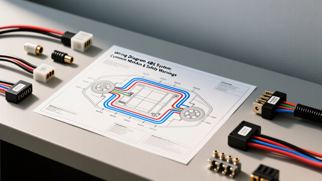
The Critical Nature of ABS Electrical Diagnostics
When troubleshooting brake faults, interpreting a wiring diagram ABS system schematic requires more than just tracing lines from point A to point B. The Anti-lock Braking System (ABS) and Electronic Brake Control Module (EBCM) are classified under ISO 26262 as ASIL D (Automotive Safety Integrity Level D), meaning they are the most safety-critical electrical systems on the vehicle. A misread schematic or an improper probing technique can lead to catastrophic brake failure, phantom ABS activation, or permanent module destruction.
According to the National Highway Traffic Safety Administration (NHTSA), ABS relies on precise microsecond timing and high-fidelity sensor data. Any electrical interference introduced by a technician's diagnostic method can corrupt this data. Below, we detail the most common, destructive mistakes technicians make when working with ABS wiring diagrams and the strict safety protocols required to avoid them.
Top 4 Fatal Mistakes When Reading a Wiring Diagram ABS System
1. Confusing Active and Passive Wheel Speed Sensors
The most frequent error occurs when a technician misidentifies the sensor type on the wiring diagram and applies the wrong diagnostic voltage.
- Passive (Variable Reluctance) Sensors: These are 2-wire sensors that generate their own AC voltage as the tone ring passes. They do not receive external power. The wiring diagram will show them returning directly to the EBCM signal and low-reference pins.
- Active (Magneto-Resistive) Sensors: These require a 5V to 12V reference supply from the EBCM to operate. They output a digital square-wave signal or a current-modulating signal (typically 7mA to 14mA).
The Mistake: A technician sees a 2-wire circuit on the diagram, assumes it is a passive VR sensor, and attempts to test it with an ohmmeter or applies 12V from a power probe. Supplying external voltage to a passive sensor will instantly short and fry the internal coil. Conversely, backprobing an active sensor with a standard test light will pull the circuit low, causing the EBCM to instantly set a hard Diagnostic Trouble Code (DTC) and disable the ABS system for the remainder of the key cycle.
2. Untwisting CAN Bus Pairs for Probing
Modern ABS modules communicate with the Powertrain Control Module (PCM) and instrument cluster via a High-Speed Controller Area Network (CAN-C). On the wiring diagram, these are identified as CAN High (typically Dark Green/White) and CAN Low (typically Dark Green).
The Mistake: To attach multimeter leads or a breakout box, technicians often untwist the wires near the EBCM connector. The SAE J2931 standard for digital communications mandates a strict twist rate (usually 1 twist per 1 to 1.5 inches) to maintain a 120-ohm characteristic impedance and cancel out electromagnetic interference (EMI). Untwisting even two inches of wire alters the impedance, causing signal reflection and ringing. This results in phantom U-codes (e.g., U0121 - Lost Communication with ABS Module) that are nearly impossible to diagnose because the fault only occurs when the vehicle is moving and generating EMI.
3. Piercing Wire Insulation on 20 AWG Signal Lines
Wheel speed sensor harnesses are typically routed through harsh environments (wheel wells, suspension components) and are manufactured using 20 AWG or 18 AWG wire with thin-wall cross-linked polyethylene (XLPE) insulation.
The Mistake: Using a standard steel test probe to pierce the wire insulation to check for a square-wave signal. This creates a microscopic hole in the jacket. Moisture and road salt wick into the stranded copper via capillary action, leading to copper oxide buildup (verdigris). Within months, this creates a high-resistance fault. The EBCM interprets this voltage drop as a failing tone ring or a bad sensor, leading to unnecessary parts replacement. Always use specialized T-pins or front-backprobes at the Metri-Pack 2.8 connector cavity instead of piercing wires.
4. Ignoring Module Ground Multiplexing and Star Points
Wiring diagrams often show multiple ground pins for the EBCM (e.g., Pins 1, 2, 14, and 15). Technicians often assume these are redundant and only test one.
The Mistake: In reality, ABS modules use dedicated, isolated ground circuits for different internal subsystems. Pin 1 might be the logic ground for the microprocessor, while Pin 14 is the high-current power ground for the hydraulic pump motor (which can draw 40+ amps). If a technician repairs a frayed ground wire but routes it to a shared chassis ground instead of the dedicated "Star Point" ground shown on the schematic, the high-current pump noise will backfeed into the logic ground. This causes the microprocessor to reset during hard braking events, resulting in a sudden, uncommanded loss of ABS function.
EBCM 40-Pin Connector Reference Chart
Below is a representative pinout specification for a common late-model domestic 40-pin EBCM connector. Always verify against your specific OEM service manual, as pinouts vary by manufacturer and model year.
| Pin | Circuit Function | Typical Wire Color | AWG Size | Connector Cavity Type |
|---|---|---|---|---|
| 1 | Battery Feed (Ignition Run/Start) | Pink / White Stripe | 12 AWG | Metri-Pack 2.8 |
| 2 | Main Battery Feed (Constant 12V) | Red | 10 AWG | Metri-Pack 6.3 |
| 14 | Pump Motor Ground | Black / White Stripe | 10 AWG | Metri-Pack 6.3 |
| 15 | Logic / Sensor Ground | Black | 14 AWG | Metri-Pack 2.8 |
| 22 | CAN High (HS-CAN) | Dark Green / White | 20 AWG | Micro-Pack 1.2 |
| 23 | CAN Low (HS-CAN) | Dark Green | 20 AWG | Micro-Pack 1.2 |
| 31 | Left Front Active Sensor Supply | Light Blue | 20 AWG | Micro-Pack 1.2 |
| 32 | Left Front Active Sensor Signal | Light Blue / Black | 20 AWG | Micro-Pack 1.2 |
Note: The 10 AWG wires for main power and pump ground require specific crimping tools and torque specifications (typically 9-12 Nm for the chassis ring terminals) to prevent voltage drop under the extreme load of the hydraulic pump motor.
Mandatory Safety Protocols Before Probing
Working on the ABS system carries inherent risks to both the technician and the vehicle's electrical architecture. Adhere to these safety warnings before disconnecting or probing any EBCM circuits:
- Capacitor Discharge Wait Time: The EBCM contains large electrolytic capacitors used to stabilize voltage for the pump motor and solenoid valves. Disconnecting the battery is not enough. You must wait a minimum of 3 minutes (refer to OEM specs, some hybrids require 10+ minutes) after battery disconnect before unplugging the main 40-pin or 54-pin harness. Probing live pins immediately after disconnect can result in a high-voltage arc that will destroy your digital multimeter (DMM) and potentially cause burns.
- Airbag System Proximity: The EBCM is frequently located in the engine bay near the firewall, sharing routing paths with the Supplemental Restraint System (SRS). SRS wiring is universally color-coded Yellow. Never probe, backprobe, or apply continuity tests to yellow wires or connectors. An accidental short or voltage spike from your DMM can deploy the airbags or seatbelt pretensioners.
- Static Electricity (ESD) Precautions: Active wheel speed sensors and the EBCM microprocessor are highly sensitive to Electrostatic Discharge. When replacing a sensor or disconnecting the main harness in low-humidity environments, wear an ESD wrist strap grounded to the vehicle's bare chassis. A static shock of just 30 volts—well below human perception—can permanently corrupt the EBCM's EEPROM memory.
Real-World Failure Modes from Diagram Misreads
Ignoring the nuances of a wiring diagram ABS system schematic leads to distinct, repeatable failure modes in the field. One common scenario involves the Stop Lamp Switch circuit. The wiring diagram will show a dual-circuit switch: one set of contacts is normally open (feeding the brake lights), and the other is normally closed (feeding the EBCM a "brake released" signal). If a technician misreads the diagram and replaces the switch with a single-circuit aftermarket variant, or misadjusts the plunger depth, the EBCM will see a logical conflict (e.g., wheel speed is 60 MPH, but the brake switch indicates "pressed"). The EBCM will respond by disabling the ABS and illuminating the dash warning light to prevent unintended brake intervention.
Furthermore, as highlighted by ISO 26262 functional safety guidelines, redundant sensor pathways must remain electrically isolated. If a technician attempts to "fix" a broken wire by splicing a left-front sensor signal into a shared ground circuit not designated on the diagram, the resulting ground loop will introduce a 60Hz AC noise ripple. The EBCM's internal bandpass filter will reject this noisy signal, resulting in an intermittent "Sensor Signal Erratic" DTC that only appears on wet roads when the alternator is under high electrical load.
Summary
Successfully diagnosing an ABS electrical fault requires strict adherence to the OEM wiring diagram, an understanding of CAN bus physics, and the use of non-destructive probing methods. Never pierce wire insulation, never untwist communication pairs, and always respect the isolated ground pathways designed into the EBCM. By treating the ABS wiring schematic as a functional safety blueprint rather than a simple map, you ensure the vehicle's braking integrity remains uncompromised.