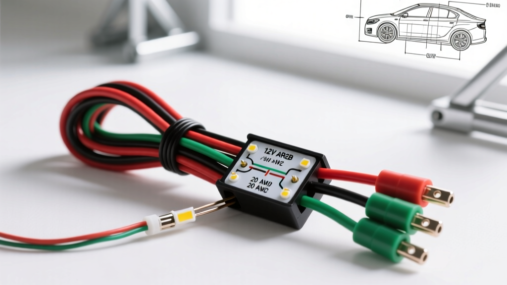
Automotive Adaptation of 3-Wire LED String Systems
When integrating custom ambient lighting, underglow, or grille halos into modern vehicles, technicians and customizers frequently require a comprehensive 3-wire led string light wiring diagram pdf to ensure safe, reliable operation. Unlike standard household 120V AC string lights, automotive 3-wire LED systems operate on 12V DC (or 5V DC via step-down buck converters) and rely on high-frequency data protocols or dual-circuit switchback logic. This technical specification reference details the exact wire gauges, pinout configurations, and electromagnetic interference (EMI) mitigation strategies required for seamless vehicle integration.
In the automotive sector, a '3-wire string light' typically refers to one of two distinct architectures: Addressable RGB (ARGB) data-driven strings (such as WS2815 12V strips) or Switchback Dual-Color DRL (Daytime Running Light) halos. Both require specialized wiring approaches to survive the harsh electrical environment of a vehicle, which is plagued by alternator ripple, load dump transients, and high-voltage ignition noise.
System Architecture: ARGB vs. Switchback DRL
1. Addressable RGB (ARGB) 3-Wire Systems
Addressable strings utilize a 3-wire topology: 12V Power, Ground, and Data. The WS2815 chipset is the automotive industry standard because it operates natively at 12V DC, eliminating the need for inefficient 5V buck converters that generate excess heat in enclosed vehicle cabins. The data line operates at 800 kHz, transmitting 24-bit color data to each individual LED node. Because the data signal is highly susceptible to Electromagnetic Interference (EMI), routing and shielding are critical.
2. Switchback Dual-Color 3-Wire Systems
Often used in headlight halos or grille lighting, switchback strings feature a common ground and two separate positive circuits (Wire 1: 6000K White DRL; Wire 2: 3000K Amber Turn Signal). When the turn signal is activated, the white circuit must be interrupted or overridden. Wiring these requires integration with the vehicle's BCM (Body Control Module) or a dedicated CAN-bus decoder to prevent hyper-flashing and bulb-out warnings.
Technical Specification & AWG Sizing Chart
Voltage drop is the primary failure point in custom automotive lighting. A standard 5-meter roll of 12V ARGB LEDs can draw up to 9 Amps at peak white output. Using undersized wire will result in dimming at the far end of the string and potential melting of the JST-SM connectors. The following chart dictates the minimum AWG (American Wire Gauge) requirements based on TXL (cross-linked polyethylene) automotive primary wire standards.
| Circuit Segment | Max Current | Wire Length (One Way) | Recommended AWG (TXL) | Voltage Drop Target |
|---|---|---|---|---|
| Main Power Trunk (Battery to Relay) | 15A | 10 - 15 ft | 12 AWG | < 0.2V |
| Relay to Controller Module | 10A | 3 - 5 ft | 14 AWG | < 0.1V |
| Controller to LED String (Pigtail) | 9A | 1 - 3 ft | 18 AWG | < 0.15V |
| Data Line (Signal) | < 50mA | Any | 22 AWG (Shielded) | N/A (Digital Signal) |
Pinout Configuration and OEM Wire Color Codes
While commercial LED strings often use arbitrary colors (e.g., Red for 5V, White for Data), automotive electrical standards dictate specific color codes to prevent catastrophic miswiring. When fabricating custom pigtails or adapting a 3-wire led string light wiring diagram pdf for a vehicle, adhere to the following SAE-compliant color mapping.
| Pin / Wire | Function (ARGB) | Function (Switchback) | Auto Wire Color | Connector Type |
|---|---|---|---|---|
| Pin 1 | 12V+ Constant / Switched | DRL White (12V+) | Red (Power) or Yellow (Switched) | Deutsch DT / JST-SM |
| Pin 2 | Data (800kHz Signal) | Turn Signal Amber (12V+) | Green (Signal) or Light Green | JST-SM (ARGB only) |
| Pin 3 | Ground (Chassis / Battery) | Common Ground | Black | Ring Terminal / Deutsch |
EMI Shielding and CAN-Bus Integration
Modern vehicles utilize a high-speed CAN-bus network (typically 500 kbps) to communicate between the ECU, BCM, and lighting modules. The 800 kHz data signal of a 3-wire ARGB string can both cause and suffer from EMI. If the unshielded data wire is routed parallel to spark plug ignition wires or the alternator output, the LEDs will exhibit 'ghosting' (random color flashes) or freeze entirely.
According to SAE J1113 standards for electromagnetic compatibility, signal wires in automotive environments must be shielded or routed at least 150mm away from high-current switching nodes. For ARGB data lines, we recommend using 22 AWG twisted-pair shielded cable, with the shield drain wire grounded at the controller end only (to prevent ground loops). Furthermore, if the lighting system is triggered by the vehicle's BCM via a PWM dimming signal, an optoisolator must be used between the BCM trigger wire and the LED controller to protect the vehicle's sensitive multiplexed circuits from voltage backfeed.
Environmental Sealing and Connector Selection
Interior ambient lighting allows for standard JST-SM 3-pin connectors. However, for exterior applications (underglow, grille strings, wheel well lighting), JST connectors will fail within months due to moisture ingress and vibration. Exterior 3-wire strings must be spliced using adhesive-lined heat shrink and terminated with Deutsch DT 3-pin connectors. The DT series features a silicone rear grommet and positive locking mechanism that withstands under-carriage pressure washing and extreme thermal cycling. Always apply dielectric grease (e.g., Nyogel 760G) to the pins before mating to prevent galvanic corrosion between copper and tin-plated terminals.
Troubleshooting Decision Tree
When a 3-wire automotive LED string fails, use this diagnostic sequence to isolate the fault:
- Symptom: LEDs are completely dead.
- Check: Inline ATC fuse at the battery. Verify 12V+ at the controller input using a multimeter.
- Fix: Replace blown fuse. If fuse blows immediately, check for pinched power wire grounding against the chassis.
- Symptom: LEDs turn on, but display random, chaotic colors.
- Check: Data line routing. Is it near ignition coils or the alternator?
- Fix: Reroute data wire or replace with shielded twisted-pair cable. Ensure the data line has a 470-ohm series resistor at the controller output to dampen signal reflections.
- Symptom: First few LEDs work, but the rest of the string is dark or dim.
- Check: Voltage at the end of the LED string. If it reads below 10.5V, you have severe voltage drop.
- Fix: Inject 12V power and Ground into both the beginning AND the end of the string using 14 AWG wire. Do not rely on the internal PCB copper traces to carry 9A over 5 meters.
- Symptom: Switchback DRL stays amber or triggers 'Bulb Out' dash warning.
- Check: CAN-bus decoder module or load resistor integration.
- Fix: Install a 6-ohm 50W load resistor in parallel with the amber turn signal wire to simulate the resistance of a halogen bulb, satisfying the BCM's diagnostic check.
Summary and Reference Materials
Successfully adapting a 3-wire LED string light to a vehicle requires moving beyond basic household wiring diagrams and respecting automotive electrical standards. By adhering to proper AWG sizing, utilizing shielded data lines, and implementing environmental sealing via Deutsch connectors, custom lighting systems can achieve OEM-level reliability. For further reading on semiconductor specifications in automotive lighting, refer to the Worldsemi WS2815 technical datasheets and your vehicle-specific Haynes or Chilton electrical manual for BCM pinout locations.