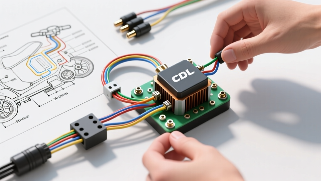
Decoding the Wiring Diagram for 50cc Scooter Electrical Systems
When troubleshooting or upgrading a 50cc scooter, understanding the underlying electrical architecture is non-negotiable. The vast majority of 50cc scooters on the road—ranging from TaoTao and Roketa to Kymco and Genuine Buddy models—rely on the ubiquitous GY6 139QMB engine platform. While these engines are mechanically simple, their electrical systems are notoriously fragile, often plagued by poor factory grounding, undersized wiring, and failing voltage regulators. This practical how-to guide will walk you through reading and applying a wiring diagram for 50cc scooter applications, focusing on the stator, regulator/rectifier, CDI, and ignition coil.
Understanding the GY6 50cc AC vs. DC Architecture
Before cutting a single wire, you must determine whether your specific scooter utilizes an AC or DC lighting system. In a standard AC system (common on budget 50cc clones), the headlight is powered directly by the stator's alternating current output. The headlight will only illuminate when the engine is running, and its brightness will fluctuate with engine RPM. In a DC system (common on premium models and aftermarket upgrades), the stator charges the battery via the regulator/rectifier, and the battery powers the headlights and horn independently of engine RPM. Finding an accurate wiring diagram for 50cc scooter models can be frustrating due to the sheer number of generic clones, but identifying the lighting system type immediately narrows down the stator wiring configuration.
Essential Wire Specifications and OEM Color Codes
Chinese-manufactured 50cc scooters generally adhere to a standardized color code, though exceptions exist. Always verify with a multimeter before splicing. Furthermore, factory wiring is often undersized, leading to voltage drop and melted connectors. When replacing harnesses, upgrade to SAE J1128 compliant primary automotive wire for superior heat and abrasion resistance.
| Circuit Function | OEM Wire Color | Recommended AWG | Technical Notes |
|---|---|---|---|
| Stator to Regulator (AC) | Yellow | 16 AWG | Carries high-current AC to the regulator. Upgrade to 14 AWG for LED lighting mods. |
| Auto-Choke Power | White | 18 AWG | Unregulated AC voltage (approx. 12V-15V AC) used to heat the wax element in the carb choke. |
| Pulse Pickup Coil | Blue/White Tracer | 20 AWG | Low voltage signal wire. Must be shielded or routed away from the ignition coil HT lead. |
| CDI Power Supply | Black/Red | 18 AWG | Raw AC voltage from the dedicated stator ignition winding. Do not connect to DC battery power. |
| System Ground | Green | 14 AWG | Engine case to frame ground. Factory 16 AWG is often insufficient; upgrade to prevent CDI misfires. |
Step-by-Step Stator and Regulator/Rectifier Installation
The stator is the heart of the 50cc scooter electrical system. A failing stator will result in a dead battery, dim lights, and eventually, a no-spark condition. Follow these steps for a bulletproof installation:
- Access the Stator Cover: Remove the left-side crankcase cover. Note the alignment dowels; losing these will cause oil leaks and improper stator air-gap alignment.
- Remove the Flywheel: You will need a universal flywheel puller (typically M27x1.0 internal thread for GY6 50cc) and a flywheel holding tool. Apply penetrating oil to the crank threads and allow it to sit for 15 minutes before applying torque to the puller.
- Swap the Stator Plate: Unbolt the three 8mm stator mounting bolts. Transfer the pulse pickup coil to the new stator if it is not pre-installed. Ensure the pickup coil gap to the flywheel reluctor tab is exactly 0.4mm to 0.6mm. A gap that is too wide will cause high-RPM misfires.
- Route the Harness: Feed the new stator wires through the rubber grommet in the crankcase. Apply a thin bead of high-temperature RTV silicone around the grommet exterior to prevent oil weeping.
- Wire the Regulator/Rectifier: The standard GY6 4-pin regulator features a Green (Ground), Yellow (Stator AC Input), Red (12V DC Output to Battery), and White (Unregulated AC to Choke) wire. Solder all connections using adhesive-lined marine heat shrink. Crimp-only connections on the Yellow wire will inevitably corrode and melt due to the high AC amperage.
Wiring the CDI Unit and Ignition Coil
The Capacitor Discharge Ignition (CDI) unit dictates the spark timing. Most 50cc scooters use an AC-fired 6-pin CDI. If you are replacing a melted harness plug, you must re-pin the connector according to the exact schematic. Miswiring the CDI will instantly destroy the internal thyristor or blow the ignition coil.
| CDI Pin Number | Wire Color | Destination / Function | Multimeter Test (Key Off) |
|---|---|---|---|
| Pin 1 | Green | Engine Ground | Continuity to engine block (< 0.5 Ohms) |
| Pin 2 | Blue/White | Pulse Pickup Coil Signal | 110 - 180 Ohms to ground |
| Pin 3 | Black/White | Kill Switch / Ignition Relay | Open circuit (12V when key ON) |
| Pin 4 | Black/Yellow | Ignition Coil Primary (+) | Continuity to coil primary terminal |
| Pin 5 | Black/Red | Stator Ignition Power (AC) | Outputs 40V-100V AC while cranking |
| Pin 6 | N/C or Pink | DC Power (DC-CDI models only) | 12V DC from ignition switch |
Note: Always verify if your CDI is AC or DC fired. An AC CDI draws power directly from the stator (Black/Red wire). A DC CDI draws power from the battery via the ignition switch. Plugging a DC CDI into an AC harness will result in zero spark.
Upgrading to a Full DC Lighting System
One of the most common modifications referenced in any advanced wiring diagram for 50cc scooter builds is the AC-to-DC lighting conversion. This mod stabilizes headlight voltage and allows the use of high-draw LED bulbs and USB charging ports. To perform this upgrade, you must rewire the stator output. Disconnect the White wire at the stator and isolate it. Take the Yellow wire from the stator and route it directly to the AC input of the regulator. The regulator's DC output (Red wire) must then be routed to a 30A relay, triggered by the ignition switch, which feeds the main DC lighting harness. This bypasses the factory headlight switch, which is typically rated for only 3 Amps and will melt under modern LED or halogen loads.
Multimeter Diagnostics for Common Failure Modes
Before replacing parts, validate the failure using a digital multimeter. According to Electrosport Industries technical guidelines, testing stator output under load is critical. Set your multimeter to AC Voltage. With the engine idling, measure between the Yellow stator wire and the engine case. You should read between 14V and 20V AC. Rev the engine to 5,000 RPM; the voltage should climb to 40V-60V AC. If the voltage remains stagnant or drops to zero when the engine gets hot, the stator winding has an internal thermal short and must be replaced.
Similarly, test the ignition coil primary and secondary windings. The primary winding (between the Black/Yellow wire and the Green ground) should read 0.5 to 1.5 Ohms. The secondary winding (measured from the spark plug cap terminal to the Green ground wire) should read 4,000 to 6,000 Ohms. A reading of infinite resistance (OL) indicates a broken internal winding, necessitating a new ignition coil. Always use a 5k-ohm resistor spark plug cap to prevent RFI interference from disrupting the sensitive CDI pickup signal.