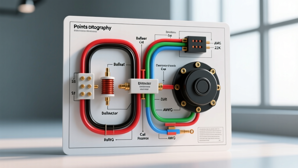
The Anatomy of a Breaker-Point Ignition Circuit
Breaker-point ignition systems remain the backbone of classic vehicle restoration, vintage racing, and agricultural machinery. Understanding the exact wiring diagram for points distributor setups requires far more than simply connecting a coil to a battery; it demands a precise balance of primary resistance, inductive saturation, and secondary voltage routing. Unlike modern distributorless or coil-on-plug (COP) systems managed by a PCM, a points-style system relies entirely on analog physics, mechanical timing, and precise electrical tolerances.
In this advanced technical deep dive, we will dissect the primary and secondary circuits, detail the critical starter bypass mechanisms, and provide exact AWG specifications, wire color codes, and diagnostic voltage-drop tests to ensure your classic V8 or inline engine fires with maximum inductive efficiency.
Primary Circuit Architecture: The Path of Current
The primary circuit is the low-voltage side of the ignition system, typically operating between 7 to 12 volts and carrying 3 to 5 amps of current. Its sole purpose is to energize the ignition coil's primary winding, creating a strong magnetic field. When the distributor's breaker points open, this magnetic field collapses, inducing the high voltage required in the secondary winding.
The standard current path follows this exact sequence:
- Battery Positive (+) to the Ignition Switch (Battery Terminal).
- Ignition Switch (Run Terminal) to the Ballast Resistor (or OEM Resistance Wire).
- Ballast Resistor Output to the Ignition Coil Positive (+) Terminal.
- Ignition Coil Negative (-) Terminal through a 16 AWG primary lead into the distributor.
- Distributor Primary Terminal to the breaker plate and tungsten contacts (points).
- Points Ground Strap to the distributor base and engine block.
Wire Gauge and Color Code Specifications
Using the correct wire gauge is critical to prevent voltage drop and resistive heating. The primary feed must handle continuous current without degrading, while the distributor lead must be flexible enough to withstand the vacuum advance plate's movement without fatiguing.
| Circuit Segment | AWG Size | OEM Color Code (Typical) | Function & Notes |
|---|---|---|---|
| Battery to Ignition Switch | 10 AWG | Red / Fusible Link | Main battery feed; must be protected by a 14-gauge fusible link. |
| Ignition Switch to Ballast | 12 AWG | Dark Blue (Mopar) / Pink (GM) | Switched 12V feed in 'Run' position. |
| Ballast to Coil (+) | 12 AWG | Dark Blue/White (Mopar) | Reduced voltage feed (approx. 7V-9V). |
| Coil (-) to Distributor | 16 AWG | Black / Braided Copper | Must be flexible; stranded copper only. Solid core will snap from vacuum advance movement. |
| Starter Bypass to Coil (+) | 14 AWG | Yellow / Red-Light Green | Full 12V bypass during cranking only. |
The Ballast Resistor and Starter Bypass Circuit
The most frequently misunderstood aspect of any wiring diagram for points distributor systems is the ballast resistor and its associated bypass circuit. Standard 12-volt points systems utilize a coil with a low internal primary resistance (typically 1.2 to 1.8 ohms). If 14.5 volts (alternator output) were applied continuously, the coil would draw excessive current (over 8 amps), rapidly burning the tungsten contacts and overheating the coil.
To prevent this, a ballast resistor (typically 1.2 to 1.8 ohms) or a specialized resistance wire (like GM's famous Pink wire) is placed in series. This drops the operating voltage at the coil to roughly 7V–9V once the engine is running.
The Cranking Bypass: 'I' vs. 'R' Terminals
When the starter motor engages, system voltage drops drastically, often to 9 volts or lower. If this reduced voltage passed through the ballast resistor, the coil would receive less than 5 volts, resulting in a weak spark and a no-start condition. To solve this, OEM engineers implemented a bypass circuit that feeds full battery voltage directly to the coil only while the starter is cranking.
- Ford / Chrysler (Mopar) / AMC: Utilize a fender-mounted starter solenoid with an 'I' (Ignition) terminal. When the solenoid engages, the 'I' terminal becomes hot, sending 12V through a 14 AWG wire directly to the Coil (+) terminal, bypassing the ballast resistor.
- General Motors (Chevy, Pontiac, Olds): Utilize a starter-mounted solenoid. The bypass originates from the 'R' (Resistance) terminal on the starter motor itself. When the Bendix drive engages, the 'R' terminal sends 12V to the coil.
Diagnostic Note: If a classic car starts while the key is held in the 'Start' position but immediately dies when the key is released to the 'Run' position, the ballast resistor is open, or the ignition switch 'Run' feed wire is broken. The engine is running solely on the starter bypass circuit. For more on classic electrical anomalies, refer to Hemmings classic ignition tech guides.
Secondary Circuit and Distributor Cap Routing
The secondary circuit handles the high-tension voltage (20,000 to 30,000 volts) generated by the coil's secondary winding. This circuit consists of the coil wire, distributor cap, rotor, and spark plug wires.
When wiring the secondary side, wire composition matters. Original equipment utilized carbon-core suppression wires to prevent Radio Frequency Interference (RFI) from disrupting the vehicle's AM radio. However, carbon core has high internal resistance (10,000+ ohms per foot), which degrades spark energy over long wire runs. For high-performance classic builds, upgrade to spiral-core (wire-wound) 8mm or 8.5mm wires. Spiral core provides less than 500 ohms per foot of resistance while utilizing a ferrite coating to suppress RFI, ensuring maximum voltage reaches the spark plug gap.
The Physics of the Condenser (Capacitor)
No wiring diagram for a points distributor is complete without the condenser. Often mistakenly believed to merely 'prevent arcing' across the points, the condenser's true function is to form an LC (inductor-capacitor) resonant circuit with the coil's primary winding.
When the points open, the magnetic field collapses. Without a condenser, the primary current would arc across the opening tungsten contacts, slowly dissipating the energy as heat. The condenser (typically rated between 0.20 and 0.28 microfarads) provides a low-resistance path for the collapsing current. This causes the primary current to oscillate rapidly, forcing the magnetic field to collapse almost instantaneously. According to Faraday's Law of Induction, the faster the magnetic field collapses, the higher the voltage induced in the secondary winding. A weak or open condenser results in a slow field collapse, yielding a weak, orange spark and heavily pitted, oxidized points. Detailed LC circuit ignition modeling can be found in SAE International technical papers on inductive discharge systems.
Component Specifications & Tolerance Chart
Use this reference chart when bench-testing components before installation. Always use a digital multimeter (DMM) with a low-ohm resolution.
| Component | Specification / Tolerance | Failure Mode Symptom |
|---|---|---|
| Ignition Coil (Primary Winding) | 1.2 Ω - 1.8 Ω (External Ballast) | High resistance causes weak spark; 0 Ω indicates internal short. |
| Ignition Coil (Secondary Winding) | 8,000 Ω - 12,000 Ω | Open circuit (infinite Ω) results in zero spark output. |
| Ballast Resistor (Ceramic Block) | 1.2 Ω - 1.8 Ω | Cracked ceramic causes intermittent open circuit under heat. |
| Condenser (Capacitor) | 0.20 µF - 0.28 µF | Low capacitance causes severe point arcing; high capacitance causes weak spark. |
| Breaker Point Gap | 0.017 in - 0.021 in | Gap too wide reduces dwell; gap too narrow causes high-RPM misfire. |
| Dwell Angle (V8 Engine) | 28° - 32° | Incorrect dwell alters coil saturation time, leading to coil overheating. |
Advanced Diagnostic Decision Tree: No-Spark Conditions
When troubleshooting a no-spark condition, avoid the amateur mistake of simply pulling a plug wire and looking for a spark. Perform these precise voltage-drop tests with the key in the 'ON' position and the engine OFF (have a helper bump the starter to close the points, or manually open/close them).
- Test 1: Voltage at Coil (+). Connect the DMM positive lead to Coil (+) and negative to the engine block. With points open, you should read battery voltage (12V) or ballast output (7V-9V). If 0V, trace backward to the ignition switch.
- Test 2: Voltage at Coil (-). Connect DMM to Coil (-). With points open, you should read the same voltage as Coil (+). If 0V, the coil primary winding is open internally.
- Test 3: Voltage Drop Across Closed Points. Bump the engine until the points are fully closed. Connect DMM positive to Coil (-) and negative to the distributor base (ground). You should read less than 0.15V. If you read 2V or higher, the tungsten contacts are oxidized, or the breaker plate ground strap is corroded. Clean the points with a dedicated point file (never sandpaper, which leaves silica deposits that will melt into the tungsten and cause arcing).
- Test 4: Primary Current Draw. If voltage checks out but spark is weak, insert an inductive DC amp clamp over the primary wire. With points closed, current should be 3.5A to 5.0A. If current is low, the ballast resistor is out of spec or the coil primary is failing.
For comprehensive multimeter testing procedures on vintage 12V systems, AutoZone's DIY ignition diagnostics provides excellent visual references for probe placement. Mastering these analog circuits ensures your classic vehicle's ignition system remains reliable, delivering a crisp, blue spark at every RPM.