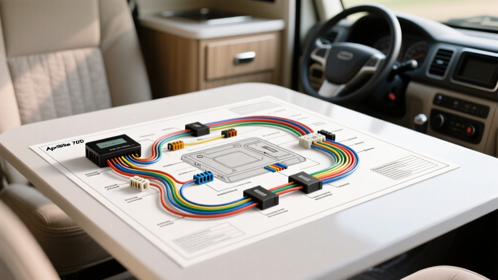
Integrating Residential Climate Control into Mobile Platforms
Custom Class A motorhomes, luxury expedition trucks (like EarthRoamer or Global Expedition Vehicles), and high-end skoolie conversions increasingly demand residential-grade climate control. When traveling through arid climates or winterizing in sub-zero temperatures, maintaining interior humidity is critical for both respiratory health and the preservation of custom wood cabinetry. The Aprilaire 700 powered whole-house humidifier is the industry standard for these applications. However, finding an accurate wiring diagram for Aprilaire 700 systems adapted for mobile automotive and RV electrical architectures is notoriously difficult.
Unlike standard residential HVAC systems that rely on a single 24V AC control board, an RV or expedition vehicle operates on a split-voltage architecture: a 12V DC chassis/house battery system and a 120V AC inverter/shore-power system. This guide provides a comprehensive product comparison, technical pinout tables, and SAE-compliant wiring methodologies to safely integrate the Aprilaire 700 into your mobile platform.
The Dual-Voltage Dilemma in Mobile Platforms
The primary challenge when installing an Aprilaire 700 in a vehicle is its dual-voltage requirement. Unlike the bypass Aprilaire 600 (which requires only 24V AC for the water solenoid), the Aprilaire 700 is a powered humidifier. It requires:
- 120V AC Power: To drive the internal blower motor that pushes air through the water panel.
- 24V AC Power: To operate the humidistat control circuit and the water solenoid valve.
In a residential home, the 120V AC is pulled from a standard wall outlet, and the 24V AC is stepped down from the furnace control board. In an RV, the 120V AC must be sourced from the coach's pure sine wave inverter or shore power bus, while the 24V AC requires a dedicated step-down transformer. Furthermore, to prevent the humidifier from draining the house battery bank during dry camping, the 120V AC circuit must be interlocked with the RV's 12V DC thermostat or ignition state.
Product Comparison: Wiring Integration Methods
Selecting the correct integration method depends on your vehicle's electrical capacity and how you plan to use the coach. Below is a comparison of the three most common wiring architectures for mobile Aprilaire 700 installations.
| Integration Method | Best Application | Hardware Required | Pros & Cons |
|---|---|---|---|
| Method A: OEM RV Branch Circuit | Class A Motorcoaches with 3000W+ Inverters | 120V to 24V AC Transformer (10VA), 14 AWG THHN Wire | Pros: Simplest wiring; uses existing RV breaker panel. Cons: Requires main inverter to be ON, causing high idle draw. |
| Method B: Dedicated Micro-Inverter | Off-Grid Expedition Trucks & Skoolies | Dedicated 400W Pure Sine Inverter, 12V DC Relay Interlock | Pros: Runs independently of main coach inverter; high efficiency. Cons: Requires additional 12V DC wiring and fusing. |
| Method C: 12V to 24V AC Solid State Module | 12V-Only Campers (No 120V AC Inverter) | 12V DC to 24V AC Power Supply, 12V DC Blower Motor Swap | Pros: Eliminates 120V AC requirement entirely. Cons: Requires voiding warranty to swap internal AC blower for DC. |
For 90% of automotive and RV applications, Method B is the superior choice. By dedicating a small, pure sine wave inverter specifically to the HVAC and humidifier circuit, you avoid the massive parasitic draw of firing up the coach's main 3000W inverter just to run a 0.5-Amp humidifier blower.
Aprilaire 700 Terminal Pinout & Wire Specifications
When referencing the standard residential wiring diagram for Aprilaire 700, mobile installers must adapt the wire gauges to account for voltage drop over the long chassis runs typical of motorhomes and expedition trailers. According to RVIA (Recreation Vehicle Industry Association) standards, all 120V AC wiring must be stranded copper and properly grounded to the vehicle chassis RFGB (Radio Frequency Ground Bus).
| Terminal / Connection | Voltage | AWG Size | Wire Color Code | Function |
|---|---|---|---|---|
| 120V AC Line (Hot) | 120V AC | 14 AWG | Black (MTW Stranded) | Powers internal blower motor |
| 120V AC Neutral | 120V AC | 14 AWG | White (MTW Stranded) | Return path for blower motor |
| 120V AC Ground | N/A | 14 AWG | Green/Bare | Safety ground to chassis |
| Transformer Primary | 120V AC | 18 AWG | Black / White | Steps down 120V to 24V AC |
| Transformer Secondary (C) | 24V AC | 18 AWG | Blue | 24V Common to Humidistat |
| Transformer Secondary (H) | 24V AC | 18 AWG | Red | 24V Hot from Humidistat |
| Water Solenoid Valve (V) | 24V AC | 18 AWG | Yellow / Orange | Opens water feed to panel |
Note: While residential installs often use solid-core 18 AWG thermostat wire, mobile environments subject to vibration and chassis flex require stranded 18 AWG wire to prevent work-hardening and internal copper fracturing over time.
Step-by-Step RV Integration: The 12V DC Interlock Relay
To ensure the Aprilaire 700 only operates when the RV's HVAC system is actively calling for heat or when the coach is connected to shore power, we use a 12V DC interlock relay. This prevents the humidifier from running down the lithium battery bank during dry camping.
Step 1: Select an RVIA-Compliant Isolated Relay
Never use a standard 12V DC automotive Bosch relay to switch 120V AC power; this violates NFPA 1192 / RVIA safety codes due to insufficient contact gap and arc suppression. Instead, use an isolated Solid State Relay (SSR) or a heavy-duty contactor with a 12V DC coil and 120V AC load contacts (e.g., Omron G7J series).
Step 2: Wiring the 12V DC Trigger Circuit
Follow SAE J1128 guidelines for low-voltage automotive wiring:
- Pin 86 (Coil +): Connect to the RV thermostat's 12V 'Fan Call' or 'Accessory' output using 16 AWG GXL Blue wire.
- Pin 85 (Coil -): Connect to the vehicle chassis ground using 16 AWG GXL Black wire.
- Pin 30 (Load In): Connect to the 120V AC Hot output from your dedicated pure sine wave inverter.
- Pin 87 (Load Out): Connect to the 120V AC Hot input on the Aprilaire 700 blower and the primary side of the 24V step-down transformer.
Step 3: Transformer Placement and Voltage Drop
Mount the 120V to 24V AC step-down transformer as close to the Aprilaire 700 terminal block as possible. Running 24V AC over long distances (e.g., 40+ feet from a basement HVAC bay to a ceiling-mounted humidifier) using 18 AWG wire will result in severe voltage drop. If the voltage at the solenoid drops below 20V AC, the valve will chatter and fail to open, leading to dry air and potential transformer burnout.
Troubleshooting Mobile Voltage Drops & Solenoid Chatter
When adapting the wiring diagram for Aprilaire 700 to a vehicle, mobile electrical technicians frequently encounter the following issues:
- Symptom: Solenoid valve hums loudly but water does not flow.
- Cause: Inverter output voltage sag under load, or excessive resistance in the 18 AWG 24V AC control wire.
- Fix: Measure AC voltage directly at the solenoid terminals while the humidistat is calling for humidity. If below 22V AC, upgrade the 24V AC secondary wiring from 18 AWG to 16 AWG stranded, or relocate the step-down transformer to within 3 feet of the humidifier unit.
- Symptom: Humidifier blower motor runs, but humidity levels do not rise.
- Cause: Water supply line is connected to the RV's cold water feed, but the water heater's recirculation loop is causing back-pressure, or the saddle valve is clogged with calcium from the RV's hard water tank.
- Fix: Install an inline 50-micron sediment filter before the Aprilaire solenoid valve, and ensure the water feed is tapped after the RV's main water pump accumulator tank to maintain consistent 40-60 PSI pressure required for the solenoid diaphragm to seat properly.
Summary
Integrating an Aprilaire 700 into an RV, expedition truck, or marine vessel requires moving beyond standard residential wiring diagrams. By utilizing a dedicated pure sine wave inverter, an RVIA-compliant 12V DC interlock relay, and stranded copper wiring to withstand chassis vibration, you can achieve reliable, automated climate control in any mobile environment. Always verify wire gauges against the specific length of your chassis runs to prevent voltage drop at the 24V AC solenoid.