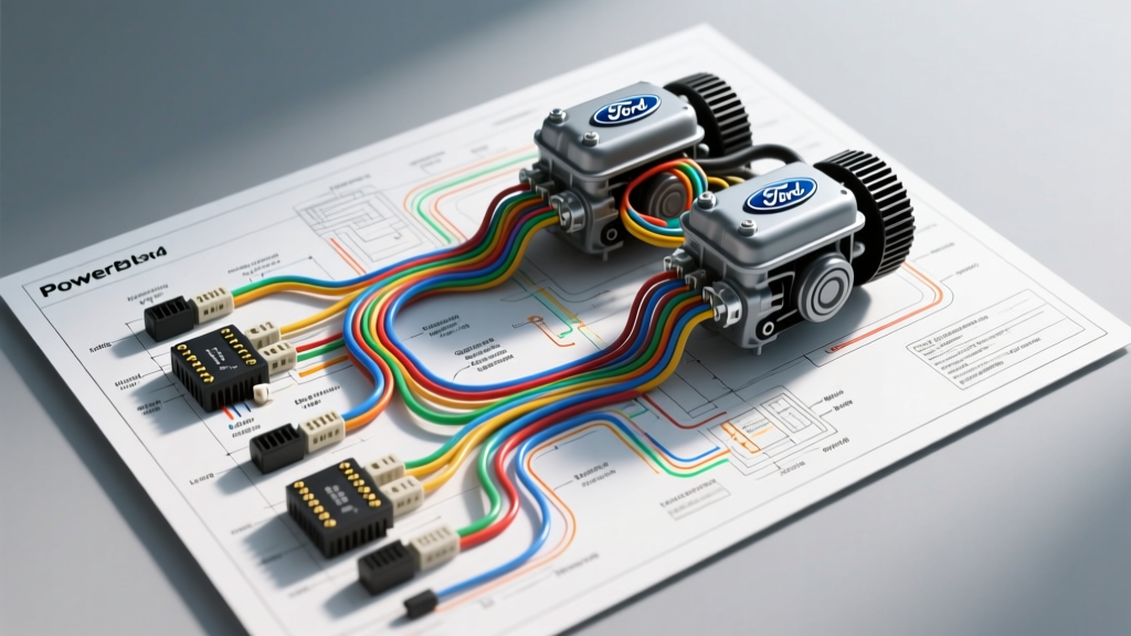
Introduction to Modern Dual-Generator Architectures
Heavy-duty diesel trucks, particularly the Ford 6.7L Powerstroke platforms, demand massive electrical output to support factory electronics, glow plug cycling, and extensive upfitter equipment. To meet these demands, manufacturers utilize a dual-generator (alternator) setup. When diagnosing charging system faults or planning an upfitter integration, relying on a generic generator wiring diagram and electrical schematics can lead to catastrophic misdiagnosis. Modern generators are not simple mechanical voltage regulators; they are sophisticated, PCM-controlled nodes communicating over a Local Interconnect Network (LIN) bus.
This complete walkthrough dissects the dual generator wiring schematic, detailing the heavy-gauge output circuits, the low-gauge communication networks, and the precise diagnostic procedures required to verify system integrity. Whether you are troubleshooting a 'Battery Not Charging' message on the dash or adding a secondary high-amp relay for a snowplow, understanding the exact pinouts and wire color codes is mandatory.
Primary vs. Secondary Generator: Schematic Overview
In a dual-generator configuration, the two units do not operate identically. The Primary Generator (typically rated between 175A and 220A) is directly integrated into the vehicle's CAN/LIN network and managed by the Powertrain Control Module (PCM). It handles the baseline chassis loads, battery maintenance, and emissions-related heating elements.
The Secondary Generator (often rated between 140A and 175A) is generally dedicated to auxiliary loads, upfitter circuits, and secondary battery banks. While it also utilizes a smart voltage regulator, its control logic is often isolated or daisy-chained differently to prevent voltage feedback loops between the two units. According to Bosch Automotive Electrics guidelines, paralleling two smart generators without proper isolation or master/slave LIN-bus arbitration will cause the regulators to 'fight' each other, resulting in severe voltage oscillation and premature diode bridge failure.
Step-by-Step Wiring Diagram Walkthrough
1. The B+ Output Circuit (Heavy Gauge)
The B+ terminal is the main power output of the generator. In the Ford 6.7L dual setup, the primary generator's B+ terminal is connected to the passenger-side battery positive post via a heavy-duty fusible link or Mega Fuse.
- Wire Gauge: 1/0 AWG (or 2/0 AWG depending on the specific model year and routing length).
- Wire Color: Black with a Red tracer (Motorcraft standard for heavy positive feeds).
- Protection: 250A Mega Fuse (Motorcraft part number WC-19390 or equivalent) located in the high-current fuse box near the primary battery.
- Torque Spec: The B+ terminal retaining nut must be torqued to exactly 12 Nm (89 lb-in). Under-torquing causes arcing and melted casing; over-torquing strips the soft brass terminal stud.
2. The Chassis Ground Circuit
Generators ground through their aluminum mounting brackets to the engine block. However, because modern engines use painted or powder-coated brackets and aluminum blocks, a dedicated ground strap is critical.
- Wire Gauge: 4 AWG braided copper strap.
- Routing: Alternator rear housing to the passenger-side cylinder head or dedicated engine block ground boss.
- Failure Mode: A corroded ground strap forces return current through the LIN-bus wiring or the alternator bearing, causing premature bearing fluting and PCM communication faults.
3. The LIN-Bus Communication Circuit
The PCM dictates the target voltage (usually between 13.5V and 14.8V, depending on battery state-of-charge and ambient temperature) via the LIN bus. As outlined in the SAE J2602 LIN Network Standard, this is a single-wire, 12V-based serial communication protocol.
- Wire Gauge: 18 AWG.
- Wire Color: White with a Light Blue tracer (WH/LB).
- Signal Type: Pulse Width Modulated (PWM) square wave. High state is typically battery voltage (approx. 12V-14V), low state is < 1.5V.
4. The Battery Sense Circuit
The generator needs to know the actual voltage at the battery terminals to compensate for voltage drop across the B+ cable. The Sense wire provides this direct feedback.
- Wire Gauge: 18 AWG.
- Wire Color: Yellow with a Light Green tracer (YE/LG).
- Routing: Fused directly from the battery positive post (usually via a 10A mini-fuse in the under-hood junction box) to the generator connector.
Connector Pinout and Wire Color Reference Table
The primary generator utilizes a 3-cavity connector (Motorcraft WPT-1245 or equivalent). Even if your specific diagram shows only two wires populated, the connector cavity remains standard across most modern LIN-controlled units.
| Pin Number | Circuit Name | Wire Color | Gauge | Function / Description |
|---|---|---|---|---|
| 1 | LIN Bus | White / Light Blue | 18 AWG | PCM communication and voltage set-point command. |
| 2 | Sense | Yellow / Light Green | 18 AWG | Direct battery voltage feedback for voltage drop compensation. |
| 3 | Ignition / Enable | Red / Yellow | 18 AWG | Switched 12V reference to wake the internal regulator (not used on all LIN-only architectures). |
Note: Always verify against the specific Motorcraft service documentation for your exact VIN, as mid-year production splits can alter wire tracer colors.
Advanced Oscilloscope Diagnostics for LIN-Bus Communication
When a scan tool indicates a 'U0129: Lost Communication With Generator' code, a multimeter is insufficient for diagnosis. You must use an automotive oscilloscope to view the generator wiring diagram's digital signals in real-time.
- Probe Setup: Connect Channel A to the LIN bus wire (White/Light Blue) at the generator harness pigtail using a back-probe. Connect the ground clip to a known-good engine block ground.
- Timebase: Set to 2 ms/division.
- Voltage Scale: Set to 5V/division.
- Expected Waveform: You should see a crisp, square-wave PWM signal. The high voltage should match the current charging system voltage (e.g., 14.2V), and the low voltage should drop to roughly 1.0V - 1.5V.
- Anomaly Detection: If the high voltage is pulled down to 8V or 9V, there is excessive resistance in the LIN circuit or a failing pull-up resistor inside the PCM. If the waveform is rounded or sloped, you have parasitic capacitance caused by a pinched wire or water intrusion in the connector cavity.
Voltage Drop Testing Procedures and Thresholds
Before condemning a generator based on electrical schematics, you must rule out cable degradation. Heavy-duty trucks are notorious for battery tray corrosion and B+ cable sulfation. Perform these tests with the engine running at 2,000 RPM and a heavy electrical load applied (HVAC on max, high-beam headlights, and rear defroster engaged).
Positive Side Voltage Drop
Place your multimeter's red lead on the generator's B+ terminal nut (not the cable ring terminal) and the black lead on the positive battery post. Acceptable Threshold: Less than 0.20V DC. If you read 0.50V or higher, the 1/0 AWG cable, the Mega Fuse, or the battery terminal clamp is compromised. The generator is working perfectly; the wiring is choking the current.
Negative Side Voltage Drop
Place the red lead on the generator's rear aluminum housing and the black lead on the negative battery post. Acceptable Threshold: Less than 0.10V DC. A reading higher than this indicates a failed engine-to-chassis ground strap or a corroded mounting bracket interface.
Summary and Best Practices
Understanding the generator wiring diagram and electrical schematics for modern dual-alternator heavy-duty vehicles requires shifting away from old-school '12V and Ground' mentalities. The integration of LIN-bus communication, remote voltage sensing, and PCM-controlled load shedding means that a wiring fault will rarely blow a fuse; instead, it will trigger a network communication code and default the generator to a safe-mode output of exactly 13.5V.
Always use dielectric grease (Motorcraft XC-3-B) on the 3-cavity connector to prevent terminal fretting corrosion, and never substitute the 18 AWG LIN-bus wire with standard primary wire, as the insulation thickness and copper stranding are critical for maintaining the specific impedance required by the SAE J2602 standard. By following this schematic walkthrough and utilizing oscilloscope verification, you can accurately diagnose and repair complex charging system faults on the first attempt.