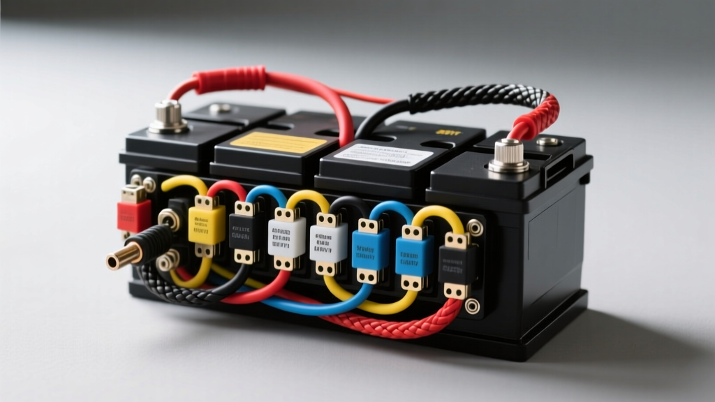
Understanding the 36V Golf Cart Battery Wiring Diagram
When working on vintage or refurbished electric vehicles, particularly the EZGO TXT or early Club Car DS models, mastering the 36v golf cart battery wiring diagram is the foundation of reliable performance. Unlike modern 48V or 72V systems, a 36-volt architecture relies on six 6-volt deep-cycle lead-acid batteries wired in a strict series configuration. This walkthrough provides a comprehensive, technician-level guide to routing, terminating, and testing the main high-current pack and low-current control circuits.
Series Wiring Architecture: The 36V Foundation
In a series circuit, voltage is cumulative while amperage capacity (Ah) remains constant. By connecting the positive terminal of one battery to the negative terminal of the next, you step up the voltage. Six 6V batteries (such as the Trojan T-105 or Crown CR-430) yield exactly 36V nominal (actually around 38.2V fully charged). If you accidentally wire two batteries in parallel within this chain, you will create a dead short, resulting in catastrophic cable melting, severe hydrogen off-gassing, and potential battery explosion.
Step-by-Step 36V Battery Wiring Walkthrough
Before touching a wrench, ensure the main tow/run switch is in the 'TOW' position and the key is off. Disconnect the primary negative cable from the battery pack first to eliminate ground paths and prevent accidental short circuits against the chassis.
Step 1: Main Battery Interconnects (High Current)
The main series links carry the full motor amperage, which can spike beyond 300A under heavy load or steep hill climbs.
- Wire Gauge: Use only 2/0 AWG (00 AWG) stranded copper cable. Do not substitute with CCA (Copper Clad Aluminum), as it suffers from higher resistance, voltage drop, and galvanic corrosion at the lead terminals.
- Routing: Connect Battery 1 Positive to Battery 2 Negative. Continue this alternating pattern through Battery 6.
- Termination: Use heavy-duty tinned copper lugs (not stamped brass). Crimp using a hydraulic hex-crimp tool to ensure a gas-tight connection that prevents moisture intrusion.
Step 2: Controller and Solenoid Integration
The main positive output from Battery 6 and the main negative output from Battery 1 route to the motor controller and high-current solenoid.
- Main Positive (Red 2/0 AWG): Routes from Battery 6 Positive to the large stud on the controller side of the main solenoid.
- Controller Negative (Black 2/0 AWG): Routes from Battery 1 Negative directly to the controller B- terminal.
- Solenoid Activation (Yellow 16 AWG): The solenoid coil requires a low-current 36V signal to close the main high-current contacts. This is typically triggered by the throttle micro-switch or the FNR (Forward/Neutral/Reverse) switch via a diode to prevent voltage backfeed into the logic circuit.
Technical Specifications and Torque Requirements
Improper torque on battery terminals is the leading cause of voltage drop and melted posts in 36V systems. Refer to the chart below for exact specifications based on SAE J1127 Battery Cable Standards and OEM manufacturer guidelines.
| Circuit Type | Wire Gauge (AWG) | Insulation Color | Terminal Torque Spec | Function |
|---|---|---|---|---|
| Main Battery Links | 2/0 AWG | Red / Black | 110 in-lbs (9.2 ft-lbs) | Series interconnects |
| Controller Main Power | 2/0 AWG | Red (Pos) / Black (Neg) | 150 in-lbs (12.5 ft-lbs) | Pack to Controller B+ / B- |
| Solenoid Coil | 16 AWG | Yellow / Blue | 35 in-lbs | Precharge & Activation |
| Key / Throttle Switch | 14 AWG | Orange | N/A (Spade Crimp) | Controller logic wake-up |
FNR Switch and Throttle Logic Wiring
In a 36V EZGO TXT with a DCS (Drive Control System) or early PDS (Precision Drive System), the throttle mechanism uses either a mechanical V-Glide resistor box or an ITS (Inductive Throttle Sensor). If wiring an ITS unit, you are dealing with a Hall-effect sensor requiring three wires: 5V reference (Red), Ground (Black), and Signal Output (White/Blue). The signal output varies from roughly 0.8V at idle to 3.6V at wide-open throttle (WOT).
The FNR switch routes the 36V pack voltage to the controller's 'Key' and 'Direction' inputs. A common failure mode is the FNR micro-switches corroding, dropping the logic voltage below 30V. This causes the controller to throw a 'Low Battery Voltage' rollback code and disable the solenoid, even when the main pack is fully charged. Always use dielectric grease inside the Deutsch or Molex connectors housing these logic pins.
Motor Terminal Connections and Reversing Rotation
Most 36V carts utilize a series-wound DC motor (e.g., Advanced DC or ADC motors). These motors feature four primary high-current terminals: A1, A2 (Armature) and S1, S2 (Stator/Field). The 2/0 AWG cables from the controller's M- and F1 terminals connect here.
To reverse the motor's rotation (if you wired the cart backward and it drives in reverse), you do NOT swap the main positive and negative battery cables. Instead, you swap ONLY the S1 and S2 stator wires relative to the armature. This reverses the magnetic field polarity while maintaining the armature current direction, effectively reversing the shaft rotation. Always use a torque wrench set to 150 in-lbs on these motor studs, as vibration from the drivetrain will easily back off improperly tightened nuts, leading to arcing and melted terminal posts.
Diagnostic Walkthrough: Testing the 36V Pack
Once the 36v golf cart battery wiring diagram is physically executed, verification is mandatory before applying a load. Use a digital multimeter (DMM) with a minimum CAT III rating.
1. Open Circuit Voltage (OCV) Verification
Measure the total pack voltage at the controller B+ and B- terminals. A fully rested, fully charged 36V lead-acid pack should read between 38.2V and 38.4V. If you read exactly 36.0V or lower immediately after charging, you have a weak cell, a sulfated battery, or a parasitic draw from a faulty charger relay.
2. Voltage Drop Testing Under Load
Static voltage does not reveal bad connections. To perform a voltage drop test:
- Set your DMM to DC Volts.
- Place the red probe on the battery post (lead part) and the black probe on the copper lug.
- Press the throttle to engage the motor (lift the rear wheels for safety).
- A healthy connection will show a voltage drop of less than 0.05V (50mV). Any reading above 0.10V indicates high resistance, requiring immediate re-crimping or terminal cleaning.
Precharge Circuits and Solenoid Protection
One of the most overlooked aspects of the 36V wiring schematic is the precharge resistor. When the solenoid closes, the controller's internal capacitors are completely discharged. Closing a 36V, 300A circuit directly into an empty capacitor bank causes a massive inrush current that will weld the solenoid contacts shut and destroy the controller's MOSFETs.
Always wire a 250-ohm, 10-watt precharge resistor across the large terminals of the main solenoid. This allows a small trickle current to charge the capacitors before the main contacts close. For deeper insights into capacitor inrush protection and deep-cycle battery maintenance, consult resources like Crown Battery University and standard EV controller manuals.
Charger Receptacle Wiring
The 3-pin or 4-pin charger receptacle must be wired directly to the main pack terminals, bypassing the solenoid and controller.
- Pin 1 (DC Positive): Wired to Battery 6 Positive.
- Pin 2 (DC Negative): Wired to Battery 1 Negative.
- Pin 3 (Charge Enable/Signal): Wired to the charger interlock circuit to prevent the cart from being driven while plugged in.
Ensure the receptacle ground is isolated from the chassis if the cart utilizes a plastic body tub, common in EZGO TXT models. For more community-driven troubleshooting and schematic variations, the archives at Buggies Gone Wild remain an invaluable resource for legacy 36V systems.
Final Inspection and Maintenance
After completing the wiring, apply a thin layer of dielectric grease or a dedicated battery terminal protectant (like NO-OX-ID A-Special) over the crimped lugs and exposed lead posts. This prevents sulfuric acid off-gassing from corroding the copper strands inside the insulation jacket. Re-check all torque specs after the first 50 charge cycles, as the lead posts will cold-flow and settle, potentially loosening the connections and initiating a thermal runaway event.