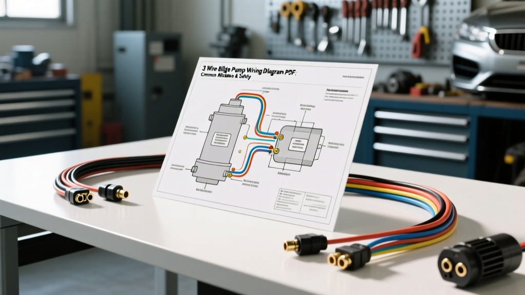
The Danger of Misinterpreting a 3 Wire Bilge Pump Wiring Diagram PDF
When enthusiasts and professionals search for a 3 wire bilge pump wiring diagram pdf, they often find generic schematics that fail to address the harsh realities of 12V DC marine and automotive crossover environments. Whether you are wiring a bilge system for an amphibious UTV, a custom overland rig with water management tanks, or a marine vessel trailer, the electrical principles remain governed by strict SAE and ABYC standards. A bilge pump is a critical safety device; its failure can result in catastrophic flooding or, conversely, an electrical fire. This guide dissects the most common, dangerous mistakes made during 3-wire bilge pump installations and provides actionable, expert-level safety warnings to ensure your system operates flawlessly when you need it most.
Standard 3-Wire Pinout and Color Code Reference
A standard 3-wire bilge pump integrates both a manual override and an automatic float switch into a single housing. This requires three distinct conductors. While automotive wiring often relies on red for power and black for ground, marine and amphibious applications follow ABYC E-11 Standards for DC color coding to prevent fatal confusion.
| Wire Function | Standard ABYC Color | Alternative MFR Color | Destination / Termination |
|---|---|---|---|
| DC Ground (Return) | Black | Black | Negative DC Bus Bar / Battery Negative |
| Manual Switch +12V | Brown | Brown | Manual Toggle Switch (Fused) |
| Auto Float Switch +12V | Brown/White Stripe | Red (Attwood/Rule) | Direct to Battery Positive via Inline Fuse |
Safety Warning: Never assume the manufacturer's color code matches ABYC standards without testing. Some budget import pumps use Red for manual and Black for auto. Always perform a continuity test with a multimeter before applying 12V power.
Critical Mistake #1: Ignoring Voltage Drop and AWG Sizing
The most frequent error found in DIY bilge wiring is using wire that is too thin for the total circuit length. A 1100 GPH bilge pump typically draws between 4.5A and 6A under load. If you use 16 AWG wire for a 20-foot run from the battery to the bilge (which equals 40 feet of total round-trip conductor length), you will experience severe voltage drop. According to SAE J1128 Low Tension Primary Cable specifications, undersized wire causes the pump motor to starve for voltage, leading to a massive drop in pumping capacity and eventual thermal burnout of the motor windings.
AWG Sizing Chart for 12V DC Bilge Pumps (5A - 8A Draw)
| Total Round-Trip Wire Length | Recommended AWG Size | Maximum Voltage Drop (3%) |
|---|---|---|
| Under 10 Feet | 16 AWG | 0.36V |
| 10 to 15 Feet | 14 AWG | 0.38V |
| 15 to 25 Feet | 12 AWG | 0.39V |
| 25 to 35 Feet | 10 AWG | 0.35V |
Critical Mistake #2: Fusing the Automatic Circuit Through the Main Switch
A 3-wire bilge pump is designed with two separate positive feeds for a reason. The manual wire (Brown) should be routed through the vessel or vehicle's main ignition or accessory switch so the operator can turn the pump on or off at will. However, the automatic float switch wire (Brown/White or Red) must be connected directly to the battery positive (or an always-hot unswitched bus bar) via its own dedicated inline fuse.
The Failure Mode: If you wire the automatic float switch feed through the main battery disconnect switch or the ignition cylinder, the automatic bilge function is disabled when the vehicle or boat is parked and unattended. If a leak develops, or rainwater fills the bilge while the system is powered down, the float switch will rise, but the circuit will remain open. The vessel will sink, or the amphibious rig will flood. The auto circuit must bypass all master switches.
Critical Mistake #3: Melting the Float Switch with High-Capacity Pumps
Many off-road and marine enthusiasts upgrade from a standard 500 GPH pump to a 2000 GPH or 3000 GPH high-capacity pump to handle heavy water ingress. A 2000 GPH pump can draw 12A to 15A under load. Standard internal or inline mechanical float switches are typically rated for a maximum of 5A to 8A.
The Safety Hazard: Passing 15A through a 5A float switch will cause the internal contacts to arc, overheat, and melt the plastic housing, resulting in a stuck pump or a localized electrical fire.
The Solution: Bosch-Style Relay Integration
When installing a high-draw pump, you must use a 12V automotive/marine relay to handle the heavy current, allowing the float switch to only carry the low-amp trigger signal.
- Pin 30 (Power In): 10 AWG wire directly from Battery Positive (Fused at 20A).
- Pin 87 (Power Out): 10 AWG wire to the Bilge Pump Auto Positive Wire.
- Pin 85 (Ground): 14 AWG wire to Negative Bus Bar.
- Pin 86 (Trigger In): 16 AWG wire from the Float Switch Positive output.
Critical Mistake #4: Using Automotive Connectors in Wet Environments
Standard automotive vinyl-insulated crimp connectors are strictly prohibited in bilge environments. In a wet bilge, water submersion and high humidity cause capillary action, wicking moisture up the copper strands and into the crimp barrel. This leads to galvanic corrosion, high resistance, and ultimate circuit failure. Furthermore, standard untinned copper wire oxidizes rapidly in marine environments.
Expert Requirement: You must use marine-grade, tinned copper wire (Type III) and adhesive-lined heat-shrink terminals. When crimped and heated, the internal adhesive melts and seals the wire barrel, completely blocking moisture ingress. Always use a ratcheting crimping tool calibrated for the specific AWG; never use standard pliers, which deform the barrel and create micro-gaps where corrosion begins.
Critical Mistake #5: Improper Grounding to the Hull or Chassis
In standard automotive wiring, the steel chassis is used as the ground return path to save wire weight and cost. In marine applications, aluminum-hulled amphibious vehicles, or fiberglass boat trailers, using the hull or chassis as a ground is a catastrophic mistake. It creates ground loops, causes severe electrolytic corrosion (stray current corrosion), and ensures the pump will fail to operate if the chassis connection rusts.
The Fix: Always run a dedicated Black ground wire from the bilge pump back to a centralized Negative DC Bus Bar, which is then tied directly to the battery negative terminal. The ground wire should be the exact same AWG as the positive feed wires.
Troubleshooting Decision Tree: Pump Fails to Activate
Use this structured diagnostic tree when your 3-wire bilge system fails to pump water:
- Symptom: Pump runs on Manual, but not on Auto.
- Cause A: Blown inline fuse on the Auto (Red/Brown-White) wire. Fix: Check fuse with multimeter; replace and investigate short circuit.
- Cause B: Float switch mechanism jammed by debris. Fix: Clean bilge sump, remove zip-ties or fishing line wrapped around the float arm.
- Cause C: Auto wire incorrectly routed through an ignition-switched bus. Fix: Reroute to always-hot battery terminal.
- Symptom: Pump hums but does not spin (Impeller stuck).
- Cause: Voltage drop due to undersized AWG or corroded ground connection. Fix: Measure voltage at the pump terminals under load. If below 11.5V, upgrade wire gauge and clean ground bus connections.
- Symptom: Pump runs continuously, draining the battery.
- Cause: Float switch stuck in the 'up' position, or internal switch shorted. Fix: Disconnect float switch wire. If pump stops, replace float switch.
Safety Warnings and Final Compliance Checklist
Before energizing any 3-wire bilge system, verify the following safety parameters to ensure compliance with West Marine and ABYC electrical best practices:
- Overcurrent Protection Placement: Fuses or circuit breakers must be installed within 7 inches of the power source (battery or bus bar) to protect the entire length of the wire.
- Wire Routing: Bilge wires must be routed above the maximum anticipated waterline. If wires must pass through the bilge, they must be encased in a sealed, watertight conduit.
- Drip Loops: Always create a drip loop before any wire enters a switch, fuse holder, or relay terminal to prevent water from traveling down the wire and into the electrical component.
- Labeling: Clearly label both the Manual and Auto fuses at the distribution panel. In an emergency, a panicked operator must know which switch controls the manual override.
By moving beyond a simple schematic and understanding the physics of voltage drop, the chemistry of corrosion, and the logic of fail-safe fusing, you ensure your 12V DC water management system remains reliable, safe, and compliant with top-tier automotive and marine engineering standards.