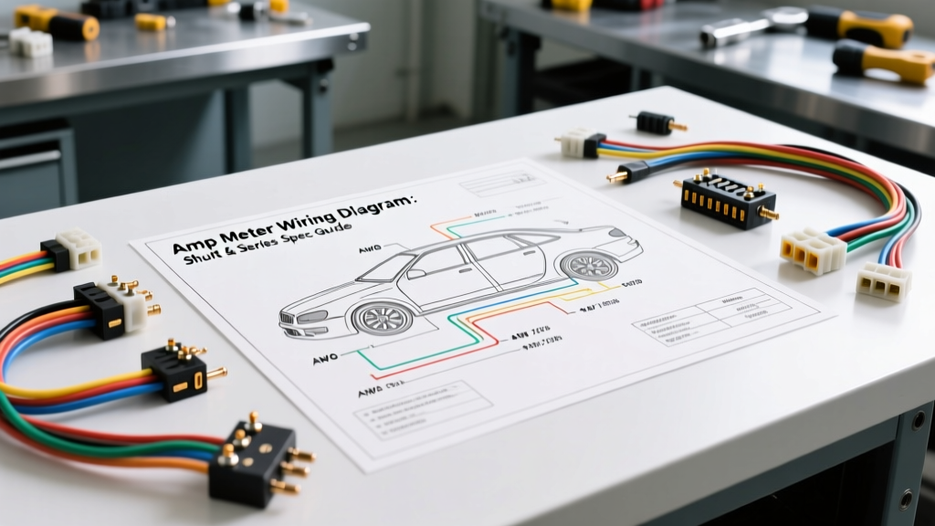
Understanding the Amp Meter Wiring Diagram Architecture
Integrating an ammeter into a classic or custom vehicle electrical system requires a precise understanding of current flow, wire gauge limitations, and terminal integrity. Unlike a voltmeter, which samples system voltage via a high-resistance parallel circuit, an amp meter measures the actual flow of electrons (current) entering or leaving the battery. Depending on the specific amp meter wiring diagram you are following, the gauge will either route the full alternator output directly through the dashboard (Series) or utilize a remote millivolt shunt (Parallel). This technical specification reference outlines the exact AWG requirements, torque specifications, and routing protocols for both architectures, ensuring your charging system operates safely without inducing voltage drop or catastrophic harness failure.
Series (Direct-Pass) Amp Meter Wiring Specifications
The series ammeter is the traditional configuration found in classic Mopar, GM, and Ford vehicles from the 1960s through the 1980s. In this architecture, the entire output of the alternator passes through the ammeter studs on the back of the dashboard before reaching the battery solenoid or main power distribution block.
Routing and AWG Requirements
Because the dashboard wiring must carry the full amperage of the charging system, wire gauge selection is critical. For a standard 60-amp alternator (such as the GM 10-SI), a minimum of 10 AWG primary cable is required. However, modern restomods frequently utilize 100-amp to 140-amp 1-wire alternators (like the Powermaster 9100). Running 100+ amps through a 10 AWG wire will cause severe voltage drop, excessive heat generation, and eventual insulation meltdown. For alternators exceeding 80 amps, you must upgrade the main charge wire and ammeter feed wires to 8 AWG or 6 AWG SAE J1128 compliant stranded copper.
Terminal and Connector Specifications
The connection points at the ammeter studs are the most common failure points in a series circuit. Do not use standard vinyl-insulated crimp terminals. Instead, utilize non-insulated, nickel-plated copper ring terminals sized for 8-10 AWG wire with a 5/16-inch or 3/8-inch stud hole. Strip the wire precisely 5/16 of an inch, insert it fully into the terminal barrel, and crimp using a ratcheting indent-style tool. Following the crimp, seal the barrel with 3:1 shrink ratio, adhesive-lined dual-wall heat shrink tubing to prevent moisture ingress and copper oxidation. Secure the ring terminals to the ammeter studs using stainless steel hex nuts and split lock washers, torqued to exactly 45 in-lbs. Over-torquing can strip the brass studs on aftermarket gauges, while under-torquing will introduce micro-arcing and localized resistance.
Shunt-Type (External Sensor) Ammeter Schematic
For high-output charging systems (150+ amps) or modern EFI vehicles where dash space and heat are concerns, a shunt-type amp meter wiring diagram is the mandatory standard. In this configuration, a heavy-duty external shunt is mounted in the engine bay, and only a low-current millivolt signal is sent to the dashboard gauge.
Shunt Placement and Heavy Cable Routing
The external shunt must be installed on the main battery ground cable or the primary positive charge cable, depending on the manufacturer's design (most automotive shunts are placed on the ground side for safety). The heavy cables connecting to the shunt must be 2 AWG or 4 AWG, terminated with heavy-duty closed-barrel lugs. The shunt itself must be mounted to a clean, bare metal surface on the chassis or engine block to ensure adequate heat dissipation, as shunts convert electrical energy into trace amounts of thermal energy.
Signal Wire Pinout and Color Codes
The sense wires running from the shunt to the dashboard ammeter carry a differential voltage typically ranging from -50mV to +50mV. Because this signal is highly susceptible to Electromagnetic Interference (EMI) from ignition systems, MSD boxes, and alternator ripple, the sense wires must be a twisted pair. Use 18 AWG twisted pair wire, routing it through the firewall via a dedicated, sealed rubber grommet. Keep the sense wires at least 6 inches away from any ignition coil primary wires, spark plug wires, or ECU harnesses. Standard color coding for the sense circuit is Red for the positive signal (+) and Black with a White tracer for the negative signal (-). Connect these to the designated screw terminals on the rear of the gauge, ensuring no stray wire strands are bridging the gap between terminals, which will short the shunt and render the gauge inoperative.
Technical Specification Reference Chart
| Parameter | Series Ammeter (Direct) | Shunt Ammeter (External) |
|---|---|---|
| Max Recommended Current | 80 Amps | 300+ Amps |
| Main Charge Wire AWG | 8 AWG to 6 AWG | 2 AWG to 1/0 AWG |
| Dash Wiring AWG | 8 AWG to 6 AWG | 18 AWG (Twisted Pair) |
| Voltage Drop Tolerance | < 0.2V at max load | < 0.05V (Signal Circuit) |
| Firewall Pass-Through | Requires Heavy-Duty Grommet | Standard 18 AWG Grommet |
| Primary Failure Risk | Dash Harness Fire | Signal Wire EMI Noise |
| Terminal Type | 5/16-inch Ring, Non-Insulated | Fork/Spade, Insulated |
| Stud Torque Spec | 45 in-lbs | 15 in-lbs (Signal Terminals) |
Diagnostic Decision Tree: Ammeter Failure Modes
When troubleshooting an automotive ammeter, follow this symptom-cause-fix decision tree to isolate the electrical fault safely.
- Symptom: Ammeter Pegged to Maximum Charge (+) Continuously
- Cause 1: Shorted Sense Wires (Shunt Type). If the positive and negative signal wires touch, the gauge reads maximum differential voltage. Fix: Inspect the twisted pair behind the dash and at the shunt for chafed insulation.
- Cause 2: Alternator Voltage Regulator Failure (Series Type). The alternator is overcharging, pushing 16+ volts into the battery. Fix: Test alternator output at the B+ terminal with a multimeter. Replace the internal or external voltage regulator.
- Symptom: Ammeter Reads Zero Under All Conditions
- Cause 1: Blown Inline Fusible Link or Main Fuse. The primary charge wire has lost continuity. Fix: Perform a voltage drop test across the main fuse or fusible link located at the starter solenoid.
- Cause 2: Open Circuit in Shunt Signal Wire. One of the 18 AWG sense wires has broken or pulled out of the crimp terminal. Fix: Use a digital multimeter set to DC millivolts to probe the shunt terminals directly while the engine is running. If mV is present at the shunt but not at the gauge, repair the broken sense wire.
- Symptom: Ammeter Needle Flutters Erratically
- Cause 1: Loose Terminal Connections. Micro-arcing at the ammeter studs or battery cables is causing rapid current fluctuations. Fix: Clean all ring terminals with a wire brush, apply dielectric grease, and re-torque to specification.
- Cause 2: EMI Interference (Shunt Type). The sense wires are routed too close to an ignition coil or alternator stator wire. Fix: Reroute the twisted pair away from high-voltage ignition components and ensure the shield (if equipped) is grounded at the gauge end only.
Installation Best Practices and EMI Rejection
Proper execution of an amp meter wiring diagram extends beyond simple connectivity; it requires strict adherence to EMI rejection protocols. Modern vehicles utilize high-energy ignition systems (HEI) and capacitive discharge boxes (e.g., MSD 6AL) that generate massive electromagnetic fields. If your ammeter signal wires act as an antenna, the gauge needle will bounce erratically with engine RPM. Always utilize a twisted pair for signal routing. The physical twisting of the positive and negative wires ensures that any induced EMI affects both wires equally, allowing the gauge's internal differential amplifier to reject the common-mode noise.
Furthermore, when passing heavy 8 AWG or 6 AWG charge wires through the firewall in a series ammeter setup, you must use a reinforced rubber firewall grommet with an internal diameter slightly smaller than the wire's outer jacket. This ensures a watertight seal that prevents moisture from wicking into the engine bay and corroding the dashboard connections. Apply a liberal coating of marine-grade dielectric grease to the ammeter studs after torquing the nuts to seal out ambient humidity and prevent galvanic corrosion between the copper terminals and brass studs.
Authoritative References
- SAE International. (2021). SAE J1128: Low Tension Primary Cable Standard. This specification defines the thermal and physical requirements for automotive copper-core wiring used in ammeter charge circuits. SAE J1128 Reference.
- Painless Performance Products. (2022). Automotive Wiring Harness Installation & Ammeter Routing Manual. Provides critical torque specs and firewall routing guidelines for high-amperage series circuits. Painless Wiring Manuals.
- Madera Concepts. (n.d.). Classic Car Ammeter Technical Guide. An authoritative resource on the failure modes of classic Mopar and GM series ammeters and the necessity of upgrading to shunt-based systems for high-output alternators. Madera Concepts Ammeter Tech.