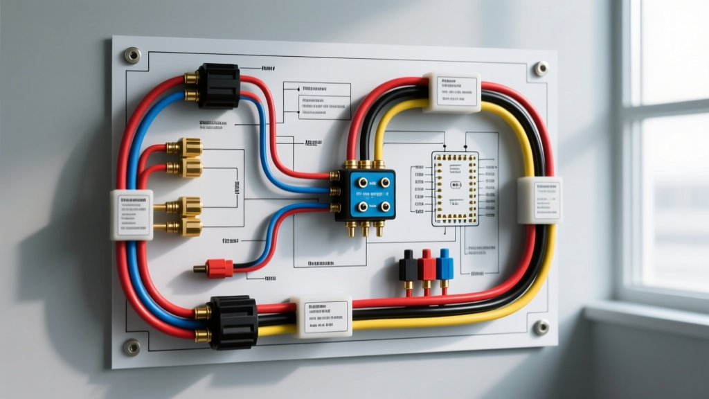
Project Overview: Upgrading Classic Vehicles for Modern A/C
When executing a restomod or upgrading a classic muscle car with a modern climate control system, relying on aging factory harnesses is a critical failure point. Original equipment wiring from the 1960s and 1970s was never designed to handle the electrical load of an aftermarket Sanden-style rotary compressor, high-CFM condenser fans, and digital servo-driven blower modules. This comprehensive guide provides the exact wiring diagram aircon methodology required to build a robust, fused, and relay-driven harness from scratch, ensuring your upgrade operates safely without melting bulkhead connectors or overloading the ignition switch.
Alternator Capacity and Primary Power Distribution
Before routing a single wire, you must verify your charging system's capacity. A modern aftermarket A/C system commands significant amperage. A typical high-output blower motor on speed four can draw 20 to 25 amps, a heavy-duty Spal condenser fan pulls 15 to 22 amps, and the compressor clutch coil requires 3.5 to 4.5 amps steady-state (with a much higher inrush current). Combined with the vehicle's existing lighting and ignition systems, a stock 60-amp externally regulated alternator will rapidly deplete the battery at idle.
For any serious wiring diagram aircon modification, upgrading to a minimum 100-amp internally regulated 1-wire or 3-wire alternator is mandatory. Run a 4 AWG primary charge wire from the alternator output stud directly to the battery positive terminal or a dedicated front-mounted mega-fuse distribution block. Never route the main A/C power feed through the factory ammeter or bulkhead connector, as the added resistance will cause severe voltage drop and potential thermal events.
The Trinary Safety Switch Logic
The heart of any safe aftermarket A/C electrical system is the trinary pressure switch. Unlike older binary switches that only protect against low refrigerant loss and catastrophic high-pressure spikes, a trinary switch adds a third circuit to engage the condenser fan at a specific medium-pressure threshold. This prevents head-pressure buildup in slow-moving traffic.
- Low-Pressure Cutoff (25 PSI): Opens the circuit to the compressor clutch relay if refrigerant is lost, preventing the compressor from running dry and destroying the internal Teflon seals.
- High-Pressure Cutoff (406 PSI): Breaks the clutch circuit if the system experiences a blockage or condenser failure, preventing hose rupture.
- Fan Engagement Trigger (254 PSI): Closes a separate internal contact to trigger the condenser fan relay, ensuring maximum airflow exactly when head pressures demand it.
The trinary switch typically utilizes a 4-pin Weather-Pack or Metri-Pack connector. Pin A and Pin B handle the series-pass for the compressor clutch trigger, while Pin C and Pin D handle the independent fan trigger. Always use dielectric grease on these connections to prevent corrosion-induced resistance.
ISO Mini Relay Pinouts and Harness Routing
Never run high-amperage loads directly through the dashboard HVAC controller or the trinary switch. These components are designed to carry low-amperage trigger signals (under 2 amps). You must use Bosch-style ISO mini relays to switch the heavy loads. According to standard automotive electrical principles, utilizing relays ensures the load receives full system voltage directly from the battery, resulting in faster clutch engagement and cooler fan motor operation.
Standard 4-Pin SPST Relay Configuration
- Pin 30 (Common): 12V+ from the battery via a dedicated inline fuse or fuse block.
- Pin 87 (Normally Open): 12V+ output to the load (compressor clutch or condenser fan).
- Pin 86 (Coil +): 12V+ switched trigger signal from the trinary switch or dashboard controller.
- Pin 85 (Coil -): Ground connection to the chassis or engine block.
When building the harness, use Tesa cloth wiring tape to wrap the looms, mimicking OEM harnesses and providing superior abrasion resistance and heat tolerance compared to standard vinyl electrical tape. For all terminations, utilize adhesive-lined heat shrink terminals. The inner layer of hot-melt adhesive seals out moisture, preventing the green crust of copper oxidation that plagues classic car engine bays.
Wiring Diagram Aircon AWG and Pinout Specification Table
The following specification table outlines the exact wire gauges, fuse ratings, and color codes required for a universal Sanden-style compressor and dual-fan condenser setup. Adhering to SAE J1128 standards for low-tension primary cable ensures the wire insulation can withstand the 125°C ambient heat radiating off the engine block and exhaust manifolds.
| Circuit Function | Wire Gauge (AWG) | Inline Fuse Rating | Recommended Wire Color | Connector Type |
|---|---|---|---|---|
| Battery to Main Distribution Block | 8 AWG | 60A MAXI Fuse | Red | Ring Terminal (5/16") |
| Relay Pin 30 to Condenser Fan | 10 AWG | 30A ATC | Red | Weather-Pack 2-Way |
| Relay Pin 87 to Compressor Clutch | 14 AWG | 15A ATC | Red | Weather-Pack 1-Way |
| Dashboard Controller to Trinary Switch | 18 AWG | 5A AGC | Yellow | Metri-Pack 150 |
| Trinary Fan Trigger to Fan Relay (Pin 86) | 18 AWG | N/A (Protected by 5A) | Blue | Metri-Pack 150 |
| All Relay Grounds (Pin 85) | 14 AWG | N/A | Black | Ring Terminal (1/4") |
Advanced Troubleshooting and Voltage Drop Testing
Even with a flawless wiring diagram aircon layout, modifications can introduce subtle electrical faults. The most common issue in aftermarket A/C installs is the compressor clutch failing to engage on hot days, despite the system being fully charged. This is rarely a refrigerant issue; it is almost always a voltage drop across the clutch coil connector.
The electromagnetic coil on a Sanden SD7 compressor requires a minimum of 12.0 volts to pull the air gap closed against the spring tension. If your wire gauge is too thin, or if you have a poor ground at the engine block, the voltage at the clutch connector may drop to 10.5 volts under load. At 10.5 volts, the magnetic field weakens, the clutch slips, generates excessive heat, and eventually burns out the coil winding.
The Voltage Drop Test Procedure
- Set your digital multimeter to DC Volts.
- Connect the red probe to the battery positive terminal and the black probe to the load side of the compressor clutch connector (back-probe the wire).
- Turn the A/C system on. The multimeter should read less than 0.5 volts. If it reads 2.0 volts or higher, you have excessive resistance in the positive feed wire or a failing relay contact.
- Next, test the ground side. Connect the red probe to the battery negative terminal and the black probe to the ground wire at the clutch connector.
- With the system engaged, a reading above 0.2 volts indicates a poor chassis ground. Clean the grounding surface with a wire brush, apply anti-oxidant paste, and secure with a star washer to bite through the paint.
For further technical validation on relay switching times and coil resistance parameters, consult the engineering bulletins provided by Vintage Air and major aftermarket climate manufacturers, which detail the precise ohm readings required for diagnostic bench-testing of A/C components before installation.
Final Integration and Harness Securing
Once all circuits are tested and verified, secure the harness away from exhaust headers, steering shafts, and sharp sheet metal edges. Use aluminum firewall pass-through grommets when routing the digital controller harness into the cabin. Never rely on zip-ties alone to secure heavy gauge wiring near moving components; utilize stainless steel P-clamps with rubber cushions bolted directly to the chassis. A properly executed wiring harness not only guarantees the longevity of your A/C upgrade but also ensures the safety of the vehicle and its occupants for decades to come.