Introduction to Aftermarket Heat Strip Upgrades
Base model commercial vans, heavy-duty truck sleepers, and specialty RVs frequently omit factory rear window and mirror defrosters. For fleet operators and owner-operators navigating freezing climates, adding aftermarket Positive Temperature Coefficient (PTC) heat strips or conductive silver-paste grids is a critical winterization modification. However, treating these high-amperage accessories like standard LED light bars is a recipe for melted switches, voltage drop, and shattered tempered glass. When engineering a reliable wiring diagram for heat strips, the electrical architecture must account for massive initial current inrush, thermal shock prevention, and robust bus-bar terminations.
This comprehensive guide details the exact circuit topology, wire gauge requirements, and relay pinouts necessary to safely integrate 12V and 24V defroster heat strips into your vehicle's electrical system. Whether you are retrofitting a Ford Transit, a Ram ProMaster, or a custom camper van, adhering to these SAE J1128 automotive wiring standards ensures longevity and optimal thermal performance.
Circuit Architecture: Why You Need a Timer and Relay
A typical rear window defroster heat strip draws between 10 and 25 amps continuously. Running this load through a standard dashboard toggle switch will rapidly degrade the switch contacts, causing internal arcing and severe voltage drop. Because heating power is proportional to the square of the voltage (P = V²/R), even a minor 1.5V drop across undersized wiring or a cheap switch will result in a 25% loss of heating output at the glass.
Furthermore, factory defroster systems utilize a 10-to-15-minute auto-shutoff timer. Leaving heat strips energized indefinitely not only drains the vehicle's battery bank but also risks thermal stress fractures in the glass substrate. Therefore, the master wiring diagram for heat strips must incorporate a heavy-duty ISO mini relay, a dedicated 12V timer delay module, and a flyback diode to protect the timer's solid-state switching transistors from inductive voltage spikes.
Core Component BOM (Bill of Materials)
- Relay: Bosch-style 5-pin ISO Mini Relay (30A/40A rated) - See TE Connectivity automotive relays for spec sheets.
- Timer Module: 12V Adjustable Delay Timer Relay (set to 12 minutes)
- Fuse: MAXI or MEGA fuse (sized 125% above max continuous draw)
- Diode: 1N4001 or 1N4004 Flyback Diode
- Wire: SAE J1128 compliant cross-linked polyethylene (XLPE) primary wire
- Terminations: Adhesive-lined heat shrink ring terminals and conductive epoxy
The Master Wiring Diagram for Heat Strips (Pinout & Routing)
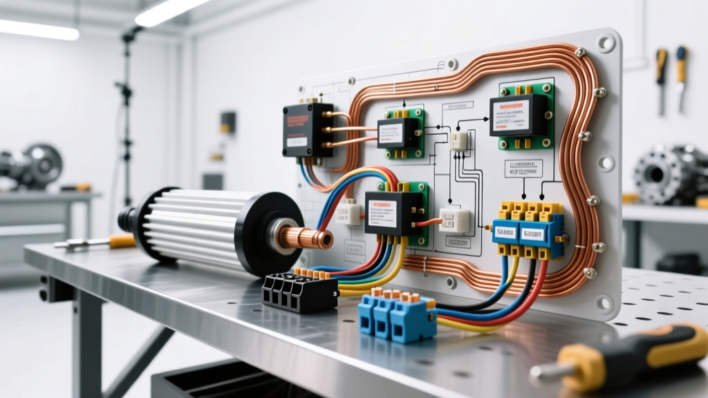
The following textual schematic outlines the precise routing for a 12V PTC heat strip upgrade. This configuration isolates the high-current load from the vehicle's sensitive CAN-bus and body control modules (BCM).
| Relay Pin | Standard Color | Connection Point | Function & Technical Notes |
|---|---|---|---|
| 30 | Red (10 AWG) | Battery Positive (+) via MAXI Fuse | Main power feed. Must be fused within 8 inches of the battery terminal. |
| 85 | Black (14 AWG) | Chassis Ground / Timer Module Ground | Relay coil ground. Ensure a clean, bare-metal grounding point. |
| 86 | Yellow/Red (16 AWG) | Timer Module Output (Trigger) | Switched 12V+ from the timer module. Place 1N4001 diode across 85/86 (stripe to 86). |
| 87 | Blue (10 AWG) | Heat Strip Positive Bus Bar | Load output. Routes directly to the defroster grid's positive tab. |
| 87a | Green (18 AWG) | Dashboard LED Indicator | Normally Closed contact. Powers a dash LED when the defroster is OFF. |
Flyback Diode Integration
When the timer module cuts power to Pin 86, the magnetic field inside the relay coil collapses, generating a reverse voltage spike that can exceed 100V. This spike will instantly destroy the MOSFET inside your aftermarket timer module. Soldering a 1N4001 diode across Pins 85 and 86 (with the cathode band facing Pin 86) creates a recirculation loop, safely dissipating the inductive kickback.
Wire Gauge (AWG) and Fuse Sizing Chart
Selecting the correct wire gauge requires calculating the total wattage of your heat strips. Side mirror PTC strips typically draw 20W each, while large rear window conductive grids can pull up to 300W. Always calculate AWG requirements based on a 14.4V running alternator voltage, not a 12.0V resting battery voltage.
| Total Strip Wattage | Amperage Draw (@14.4V) | Recommended Wire Gauge (Up to 10ft) | Required Fuse Size |
|---|---|---|---|
| 100W (Mirrors only) | 6.9 Amps | 16 AWG | 10A Mini |
| 150W (Small Rear Glass) | 10.4 Amps | 14 AWG | 15A ATO |
| 300W (Standard Rear Van) | 20.8 Amps | 10 AWG | 25A MAXI |
| 500W (Heavy Duty / RV) | 34.7 Amps | 8 AWG | 40A MEGA |
For runs exceeding 15 feet from the battery to the rear glass, step up one AWG size to mitigate voltage drop. Reference Littelfuse automotive fuse guidelines to ensure your fuse holder is rated for the high-heat environment of an engine bay or chassis rail.
Bus Bar Termination and Soldering Protocols
The most common point of failure in any defroster wiring diagram for heat strips is the physical connection to the glass-mounted bus bars. Automotive tempered glass acts as a massive heat sink. Attempting to solder a 10 AWG wire to a silver-paste bus bar with a standard 40W electronics soldering iron will result in a cold, brittle solder joint that will vibrate loose within weeks.
Professional Termination Steps
- Surface Preparation: Clean the bus bar with isopropyl alcohol and lightly scuff it with 1000-grit sandpaper to remove oxidation.
- Flux Application: Apply a generous amount of rosin-based electronic flux to the bus bar. Never use acid-core plumbing flux, as it will corrode the silver paste and shatter the glass.
- High-Wattage Soldering: Use a 100W+ temperature-controlled soldering station or a butane-powered iron. Pre-tin the 10 AWG wire with 60/40 leaded solder (which flows at lower temperatures and resists vibration fatigue better than lead-free).
- Heat Transfer: Apply the iron to the bus bar and wire simultaneously. Once the solder flows, hold the wire perfectly still for 15 seconds while the joint cools.
- Strain Relief: Secure the wire 2 inches away from the solder joint using high-strength automotive double-sided tape or a dab of structural urethane adhesive to prevent mechanical leverage from tearing the bus bar off the glass.
Troubleshooting and Diagnostics
If your heat strips fail to generate adequate thermal output, do not immediately assume the grid is defective. Use a digital multimeter (DMM) to perform the following diagnostic sequence:
- Voltage Drop Testing: With the system energized, place your DMM probes on the battery positive terminal and the heat strip positive bus bar. A reading above 0.5V indicates undersized wiring or corroded fuse terminals. Repeat on the ground side.
- Resistance Mapping: Disconnect the power and measure the resistance (Ohms) across the bus bars. A healthy 150W 12V strip should read approximately 0.96 Ohms (R = V²/P). If the DMM reads 'OL' (Open Loop), there is a micro-fracture in the conductive grid. If it reads near 0.0 Ohms, the grid has shorted internally.
- Thermal Imaging: Use an infrared thermal camera to scan the glass while the strips are active. Dark, cold bands across the glass indicate broken conductive traces that can be repaired using a conductive silver epoxy resin kit.
Summary
Executing a flawless wiring diagram for heat strips requires moving beyond simple switch-and-wire logic. By integrating ISO mini relays, flyback diodes, auto-shutoff timers, and adhering to strict AWG and soldering protocols, you ensure your aftermarket defroster upgrade operates safely and efficiently for the lifespan of the vehicle. Always verify your specific vehicle's alternator capacity before adding high-amperage thermal loads to the electrical system.