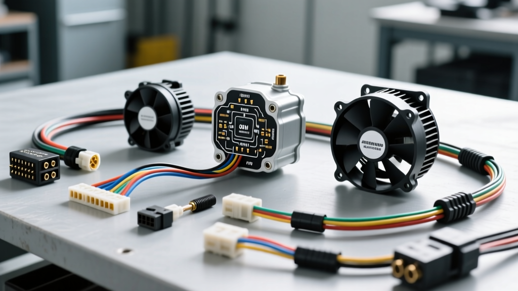
Introduction to Automotive 3-Speed Blower Motor Circuits
When designing, repairing, or upgrading an automotive HVAC system, understanding the wiring diagram 3 speed fan motor configurations is critical for reliable climate control. Whether you are restoring a classic Chevy C10, troubleshooting a failed 1990s Ford F-150 blower circuit, or installing a high-output universal aftermarket HVAC kit like a Vintage Air Gen IV, the blower motor circuit must handle significant electrical loads. A standard automotive blower motor operates on a 12V DC negative-ground system, but controlling its speed requires either stepping down the voltage via a resistor network or switching independent power feeds via relays.
In this comprehensive selection and setup guide, we compare the two dominant 3-speed fan motor architectures: the traditional ceramic resistor pack and the modern high-amp relay-based controller. We will provide exact wire color codes, AWG sizing requirements based on SAE standards, connector selections, and step-by-step wiring schematics to ensure your fan motor operates safely without melting switches or harnesses.
Resistor Pack vs. Relay-Based Fan Controllers
Before cutting and crimping wires, you must select the correct control topology for your specific motor's amperage draw. The wrong choice will result in catastrophic thermal failure of the dashboard switch or the wiring harness.
Option A: The Classic Ceramic Resistor Block (OEM Style)
The traditional OEM method uses a blower motor resistor pack, typically mounted directly in the HVAC airbox to utilize the blower's airflow for cooling. The dashboard switch routes 12V power through different taps on the resistor coil.
- Low Speed: Power passes through the entire resistor coil (approx. 1.5 to 2.0 ohms), dropping the voltage at the motor to roughly 5V-7V.
- Medium Speed: Power bypasses the first stage, passing through a smaller section of the coil (approx. 0.5 ohms), delivering roughly 9V-10V to the motor.
- High Speed: The switch completely bypasses the resistor pack, sending full 12V battery voltage directly to the motor via a dedicated high-speed relay or heavy-gauge switch contact.
Best For: Stock replacement motors drawing under 12 amps. Drawback: Resistor packs generate massive heat. If the blower motor bearings dry out and amperage spikes, the resistor block will overheat and melt the plastic connector pigtail.
Option B: High-Amp Relay Fan Control Module (Aftermarket/Heavy Duty)
For high-output aftermarket blowers (drawing 15A to 25A) or custom hot rod builds where running heavy-gauge wire through the firewall to a dashboard switch is impractical, a relay-based 3-speed controller is superior. The dashboard switch only carries the low-amperage coil trigger current (approx. 150mA per relay), while heavy-duty 30A ISO relays mounted in the engine bay handle the actual motor load.
Best For: High-amp aftermarket motors, custom rod builds, and eliminating dashboard switch heat. Drawback: Requires more wiring, multiple relays, and a larger physical footprint in the engine bay.
Wiring Diagram: 3 Speed Fan Motor Pinouts & Connections
Below is the master reference table for wiring a standard 3-speed blower motor circuit using SAE J1128 compliant automotive primary wire. This table applies to both OEM resistor setups and relay-triggered configurations.
| Circuit Function | SAE Wire Color | Min. AWG Size | Connector Type | Terminal / Pin Destination |
|---|---|---|---|---|
| Main Battery Feed (B+) | Red | 10 AWG | Ring Terminal | Fuse Box / Battery (+) Post |
| Ignition Switched 12V | Pink | 14 AWG | Weather-Pack | HVAC Control Head (Switch Input) |
| Low Speed Tap | Light Blue | 14 AWG | Metri-Pack 280 | Resistor Pack Pin 1 / Relay 1 Coil |
| Medium Speed Tap | Tan / Yellow | 14 AWG | Metri-Pack 280 | Resistor Pack Pin 2 / Relay 2 Coil |
| High Speed Bypass | Orange | 10 AWG | Spade / Ring | Motor (+) Terminal / Relay 3 Output |
| Motor Ground | Black | 10 AWG | Ring Terminal | Clean Chassis Ground / Engine Block |
Component Selection Guide: Matching the Motor to the Controller
Selecting the right components prevents voltage drop, ensures proper blower RPM, and prevents electrical fires. Follow these engineering guidelines when sourcing parts for your 3-speed fan motor wiring diagram.
1. Calculating Amperage and Wire Sizing
Always measure the blower motor's maximum amperage draw on a bench using a digital multimeter (DMM) with a 10A or 20A shunt before finalizing your wire gauge. According to SAE J1128 standards for low-tension primary cable, wire gauge must be selected based on the length of the run and the maximum continuous current. For a standard 15-amp blower motor located under the dash with a 10-foot total circuit length, 12 AWG GXL wire is the absolute minimum, though 10 AWG is highly recommended to prevent a voltage drop greater than 0.5V, which would noticeably reduce high-speed airflow.
2. Connector Selection for High-Vibration Environments
Never use standard vinyl-insulated crimp connectors for under-hood or airbox-mounted blower motor circuits. The thermal cycling and moisture exposure will cause corrosion and capillary wicking. Instead, use sealed connector systems. Aptiv (formerly Delphi) Weather-Pack connectors feature silicone ribbed seals that prevent moisture ingress and are rated for continuous high-amperage automotive HVAC use. For the resistor block pigtail, use genuine OEM-style ceramic housings with brass terminals, as standard plastic housings will melt from the radiant heat of the resistor coils.
Step-by-Step Relay Wiring Guide (The Alternative Diagram)
If you are bypassing a melted OEM switch or upgrading to a high-amp motor, you must wire three standard Bosch-style 5-pin ISO micro-relays. Here is the exact pinout logic for the relay-based 3-speed fan motor setup:
- Relay 1 (Low Speed): Pin 86 to Ignition 12V. Pin 85 to Dashboard Switch "Low" output. Pin 30 to 12V Battery Feed (via 15A fuse). Pin 87 to Motor (+) via a heavy-duty inline power resistor (to drop voltage for low speed). Pin 87a unused.
- Relay 2 (Medium Speed): Pin 86 to Ignition 12V. Pin 85 to Dashboard Switch "Med" output. Pin 30 to 12V Battery Feed (via 20A fuse). Pin 87 to Motor (+) via a secondary, lower-ohm resistor. Pin 87a unused.
- Relay 3 (High Speed): Pin 86 to Ignition 12V. Pin 85 to Dashboard Switch "High" output. Pin 30 to 12V Battery Feed (via 30A fuse). Pin 87 directly to Motor (+). Pin 87a unused.
Expert Note: When wiring the relay coils (Pins 85 and 86), it is best practice to wire a reverse-biased flyback diode (e.g., 1N4007) across the coil terminals to suppress inductive voltage spikes that can damage solid-state dashboard switches or modern ECU logic boards.
Common Failure Modes and Multimeter Diagnostics
When troubleshooting an existing 3-speed fan motor wiring diagram, use this diagnostic decision tree to isolate the fault:
- Symptom: Fan only works on High Speed.
Diagnosis: The high-speed circuit bypasses the resistor pack. This almost universally indicates a failed blower motor resistor block or a melted connector pigtail at the resistor. Inspect the Light Blue and Tan wires for thermal discoloration. - Symptom: Fan works on Low and Medium, but not High.
Diagnosis: The high-speed relay has failed, the 30A high-speed fuse is blown, or the dashboard switch contacts for the high-speed detent are burnt. Perform a voltage drop test across the switch contacts; a reading above 0.2V indicates internal switch resistance. - Symptom: Fan speed does not change, runs full speed on all settings.
Diagnosis: The resistor coil has shorted internally, or the wiring harness has chafed against the chassis, causing the Low and Medium tap wires to short directly to the 12V B+ feed.
Authoritative References
For further engineering data on automotive electrical systems, wire sizing, and HVAC component specifications, consult the following resources:
- SAE International - J1128: Low Tension Primary Cable (Wire gauge and thermal rating standards).
- Vintage Air Technical Bulletins (Aftermarket high-amp blower motor installation and relay wiring schematics).
- Mouser Electronics - Aptiv Weather-Pack Specifications (Automotive sealed connector torque and crimp data).