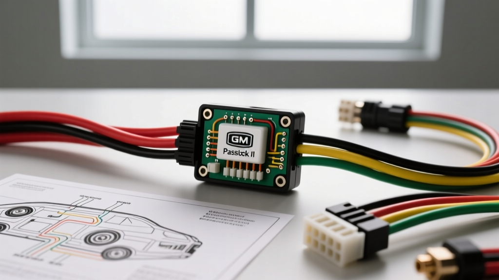
Understanding the GM Passlock II Theft Deterrent System
The General Motors Passlock II system, prevalent in models from 1999 to 2006 (including the Chevy Silverado, Pontiac Grand Am, Saturn Ion, and Chevy Cobalt), is a highly misunderstood immobilizer architecture. Unlike the older VATS (Vehicle Anti-Theft System) which relied on a visible resistor pellet on the mechanical key blade, Passlock II embeds a Hall Effect sensor and a fixed resistor matrix directly inside the ignition lock cylinder housing. When the mechanical key turns the lock cylinder, a small magnet passes the Hall Effect sensor, closing a circuit and allowing the Theft Deterrent Module (TDM) or Body Control Module (BCM) to read a specific voltage drop across the resistor. If the SAE International J2944 Standard for immobilizer communication is not met, the TDM disables the fuel injectors via the Class 2 serial data bus.
The most common failure point in this system is not the ignition switch itself, but the micro-wiring harness that connects the lock cylinder sensor to the steering column main harness. Repeated steering column articulation and key insertions cause the 22 AWG wires to fatigue, snap, or develop high-resistance corrosion. This guide provides a comprehensive step-by-step troubleshooting flow, the exact theft deterrent ignition switch wiring passlock bypass diagram specifications, and the mandatory relearn procedure.
Passlock II Ignition Switch Wiring Pinout & Specifications
Before initiating the troubleshooting flow, you must understand the 3-wire Passlock sensor circuit. This circuit connects directly to the TDM (or BCM, depending on the specific GM platform). The connector is typically a 3-pin weather-pack style pigtail located near the base of the ignition lock cylinder.
| Pin / Cavity | Wire Color | AWG Size | Function & Voltage Parameters |
|---|---|---|---|
| A (or 1) | Black | 20 AWG | Sensor Ground. Must read less than 0.05V drop to chassis ground. |
| B (or 2) | Yellow | 22 AWG | Passlock Data / Signal Circuit. Carries the voltage drop signal to the TDM. |
| C (or 3) | Orange/Black (or Red/White) | 22 AWG | 5-Volt Reference from TDM. Supplies power to the sensor matrix. |
Note: Always verify wire colors against your specific vehicle's factory service manual, as GM occasionally substituted Orange/Black with Red/White on later 2004-2006 platforms.
Step-by-Step Troubleshooting Flow
Follow this diagnostic decision tree to isolate the fault before attempting a bypass. Bypassing a system with a faulty TDM or broken Class 2 data line will not resolve a no-start condition.
Phase 1: Symptom Verification & Dashboard Indicators
- Symptom A: Engine cranks but does not start. 'Security' light flashes rapidly on the instrument cluster. Diagnosis: TDM is actively blocking fuel injectors due to an invalid Passlock code or open circuit.
- Symptom B: Engine starts, runs for exactly 1-2 seconds, then dies. 'Security' light illuminates solid. Diagnosis: TDM received an initial valid code, but lost the signal during the crank voltage drop. Usually indicates high resistance or an intermittent break in the Yellow signal wire.
- Symptom C: No crank, no dash lights. Diagnosis: This is NOT a Passlock issue. Passlock only disables fuel, not the starter circuit. Check the neutral safety switch and main ignition switch power feeds.
Phase 2: Multimeter Diagnostics at the TDM Connector
According to NHTSA Anti-Theft Device Guidelines and GM service literature, you must test the circuit under load. Do not rely solely on resistance (Ohms) testing, as a failing wire may pass a static Ohm test but fail under the 5V reference load.
- Access the Harness: Remove the upper and lower steering column shrouds. Disconnect the negative battery terminal and wait 3 minutes to depower the SIR (Supplemental Inflatable Restraint) airbag system.
- Test the 5V Reference: Reconnect the battery. Set your Digital Multimeter (DMM) to DC Volts. Backprobe the Orange/Black wire at the lock cylinder connector. Key ON, Engine OFF (KOEO). You should read exactly 4.8V to 5.2V. If 0V, the TDM is dead or the wire is shorted to ground.
- Test the Signal Circuit (Yellow): Backprobe the Yellow wire. KOEO, it should read roughly 5V (pull-up voltage). Have an assistant turn the key to the CRANK position. The voltage should drop to a specific threshold (typically between 2.0V and 4.0V, depending on the specific resistor code of your cylinder). If it drops to 0V or remains at 5V during crank, the internal sensor or the wiring pigtail is open.
Executing the Passlock Bypass (Fixed Resistor Method)
If the lock cylinder sensor has failed internally or the steering column harness is damaged beyond simple repair, you can bypass the theft deterrent ignition switch wiring using a fixed resistor. This tricks the TDM into reading a permanent, valid voltage drop. For deeper wiring tutorials, refer to Haynes Automotive Electrical Tutorials.
Required Tools and Materials
- Digital Multimeter (DMM) with 0.1 Ohm resolution
- 1/4 Watt Carbon Film Resistor Assortment (or a Decade Resistance Box)
- 22 AWG Stranded Copper Wire (to match factory gauge)
- Rosin-core solder and adhesive-lined marine-grade heat shrink tubing
- Wire strippers and flush cutters
Bypass Wiring Procedure
- Isolate the Sensor: Locate the 3-wire Passlock pigtail near the ignition lock cylinder. Cut the Yellow and Orange/Black wires about 2 inches from the lock cylinder connector. Do not cut the Black ground wire.
- Measure the Cylinder Resistance: Set your DMM to Ohms. Place your probes directly into the Yellow and Orange/Black cavities on the lock cylinder side of the cut harness. Turn the key to the ON position. Record the exact resistance reading (e.g., 4.32 kΩ). This is your target bypass resistance.
- Prepare the Bypass Harness: On the vehicle harness side (the side leading back to the TDM), strip 1/4 inch of insulation from the Yellow and Orange/Black wires.
- Install the Resistor: Select a fixed resistor that matches your measured value within 5%. Solder the resistor between the vehicle-side Yellow wire and the vehicle-side Orange/Black wire. Use 22 AWG jumper wires if the resistor leads are too short. Cover the entire connection with adhesive-lined heat shrink to prevent moisture ingress and vibration-induced shorts.
- Secure the Wiring: The TDM constantly monitors for sudden resistance spikes. If the resistor vibrates against the steering column shaft, it can cause a momentary open circuit, instantly killing the engine while driving. Securely zip-tie the bypass harness to the main column loom, ensuring a minimum 2-inch bend radius to prevent wire fatigue.
Mandatory 30-Minute Passlock Relearn Procedure
Completing the physical bypass is only half the repair. The TDM has stored the open-circuit fault and will continue to disable the fuel injectors until a formal relearn is executed. This process forces the TDM to sample the new fixed resistor voltage drop and write it to the EEPROM memory.
- Ensure the vehicle battery is connected to a clean, stable 12V power supply or battery maintainer. A voltage drop below 11.5V during the relearn will corrupt the process.
- Turn the ignition key to the ON position (do not crank the engine). Observe the 'Security' light on the dash.
- Attempt to start the engine. It will crank, start, and immediately stall. Leave the key in the ON position.
- Watch the 'Security' light. It will flash for approximately 10 minutes, then turn OFF or change to a solid state. This indicates the TDM has sampled the new resistor code.
- Turn the key OFF and wait exactly 5 seconds.
- Repeat Steps 2 through 5 two more times, for a total of three 10-minute cycles (30 minutes total).
- After the third cycle, turn the key OFF, wait 5 seconds, and then crank the engine. The vehicle should start and run normally, confirming the theft deterrent ignition switch wiring passlock bypass diagram procedure was successful.
Expert Warning: If the vehicle fails to start after the 30-minute relearn, verify your solder joints. A cold solder joint will introduce fluctuating resistance, which the TDM will interpret as a tamper attempt, locking the system down further. Always use a torque wrench set to 22 Nm when reinstalling steering column shroud bolts to prevent pinching the newly bypassed harness.