The Challenge of AC Baseboard Heaters in Off-Grid Vehicles
Integrating residential-style 120V AC electric baseboard heaters into a camper van, skoolie, or expedition RV is a popular upgrade for off-grid builders seeking silent, draft-free heating. Unlike forced-air diesel heaters, baseboard units have zero moving parts, making them ideal for sleeping areas and pet-friendly rigs. However, the electrical demands are immense. A standard 1500W baseboard heater draws 12.5 amps at 120V AC. When factoring in inverter inefficiencies, this translates to a continuous DC draw exceeding 135 amps from a 12V battery bank.
Standard residential wiring electric baseboard heaters diagrams do not account for vehicular vibration, DC-to-AC inversion losses, or the strict grounding requirements of a rolling chassis. To execute this modification safely and prevent catastrophic thermal events or inverter failure, you must bridge the gap between residential electrical theory and marine-grade automotive standards. This guide provides the exact schematics, AWG specifications, and component configurations required to wire 120V baseboard heaters via a high-capacity pure sine wave inverter.
System Architecture & Schematic Overview
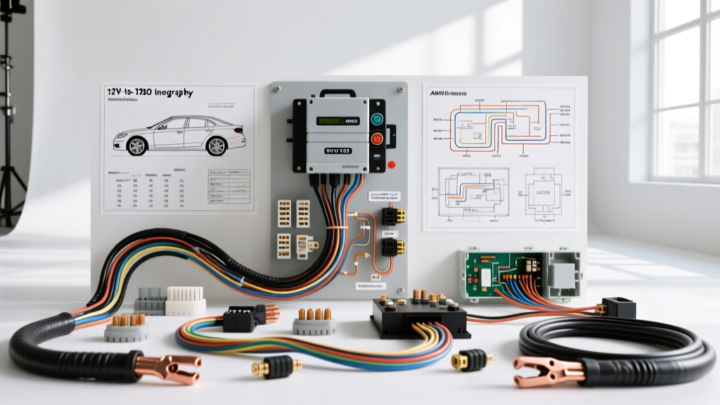
Before running any wire, you must understand the complete circuit topology. The system is divided into two distinct domains: the high-current DC supply side and the 120V AC distribution side. Below is the structural flow of our custom wiring electric baseboard heaters diagrams for a 3000W inverter setup.
- DC Domain: Lithium Battery Bank (BMS) → Main Class T Fuse → Heavy-Duty Busbars → 3000W Pure Sine Wave Inverter.
- AC Domain: Inverter AC Out → RV AC Subpanel → 12 AWG Stranded THHN → Heavy-Duty Contactor Relay → Line-Voltage Thermostat → Baseboard Heater Element.
According to the NFPA 1192 Standard on Recreational Vehicles, all AC and DC wiring must be secured every 18 inches and protected against chafing. Furthermore, solid-core Romex wire is strictly prohibited in vehicular applications due to metal fatigue and strand breakage caused by road vibration.
DC Side Wiring Specifications (Battery to Inverter)
The DC side of this upgrade is where most DIY builders fail. A 1500W heater pulling through a 90% efficient inverter requires roughly 138 amps of continuous DC current. Voltage drop over long cable runs will trigger the inverter's Low Voltage Disconnect (LVD), shutting off the heater unexpectedly.
DC Component Sizing & Torque Chart
| Component | Specification | Torque Spec | Technical Notes |
|---|---|---|---|
| Main Battery Fuse | 200A Class T | N/A | Must meet SAE J1171 ignition protection standards. Place within 7 inches of the battery positive terminal. |
| Inverter Cables | 2/0 AWG Welding | 15 Nm (11 ft-lbs) | Tinned copper, 105°C rating. Use closed-loop lugs with 3/8" holes. |
| DC Busbars | 250A Rated | 12 Nm (9 ft-lbs) | Must be covered to prevent accidental shorting. Mount on non-conductive backplate. |
| BMS Shunt | 500A / 50mV | 10 Nm (7.4 ft-lbs) | Required for accurate State of Charge (SoC) monitoring under high DC loads. |
Always reference the Victron Energy Wiring Unlimited Guide for precise crimping techniques. A poorly crimped 2/0 AWG lug will generate immense heat at 138 amps, potentially melting the insulation and causing a chassis short.
AC Side Wiring & Vibration Mitigation
Once the DC power reaches the inverter and is converted to 120V AC, the wiring methodology must shift to accommodate vehicular movement. Residential baseboard heaters typically use 14/2 or 12/2 solid-core NM-B (Romex) cable. Never use solid-core wire in an RV or camper van.
AC Wiring Best Practices
- Wire Type: Use 12 AWG stranded THHN wire. Stranded wire flexes with the chassis and resists metal fatigue.
- Conduit: Route all AC THHN wires through Liquid-Tight Flexible Metallic Conduit (LFMC) or split nylon loom to prevent abrasion against the vehicle's ribbed steel floor.
- Connections: Standard wire nuts will vibrate loose over time, leading to high-resistance arcing. Use Wago 221-series lever nuts (rated for vibration per IEC 60998) or marine-grade adhesive-lined heat shrink butt splices for all in-line connections.
- Grounding: The AC ground (green wire) must terminate at the inverter's AC ground bus, which is internally bonded to the DC ground. Do not bond the AC neutral to the chassis ground, as this will trip the inverter's internal GFCI/RCD and cause stray AC currents on the vehicle body.
Thermostat Integration & Contactor Logic
Standard residential line-voltage thermostats use a bimetallic strip to switch the 120V load. In a moving vehicle, the vibration can cause the contacts to chatter, creating micro-arcs that will quickly weld the thermostat contacts shut, resulting in a runaway heater that cannot be turned off. Furthermore, many inverters output a modified sine wave, which causes severe humming and overheating in resistive heating elements controlled by solid-state or bimetallic switches.
The Solution: Use a low-voltage 12V smart thermostat (such as a Shelly 1 or a standard 12V RV thermostat) to trigger a 120V AC heavy-duty contactor relay (e.g., Schneider Electric 8903 series). The thermostat switches the 12V coil of the contactor, while the contactor's heavy-duty silver-alloy contacts handle the 12.5A AC load of the baseboard heater. This isolates the delicate thermostat from the high-current AC vibration environment and ensures reliable, arc-free switching.
BMS and Inverter Configuration for High Loads
Wiring the physical components is only half the battle; configuring the software parameters is critical to prevent a BMS hard-shutdown. If a lithium BMS hits its low-voltage cutoff and opens its internal MOSFETs while the inverter is pulling 138 amps, the resulting inductive voltage spike can instantly destroy the inverter's capacitors.
Parameter Synchronization Table
| Parameter | BMS Setting | Inverter Setting | Reasoning |
|---|---|---|---|
| Low Voltage Disconnect (LVD) | 11.2V | 11.6V | Inverter must shut down before the BMS to prevent inductive spikes. |
| High Voltage Disconnect (HVD) | 14.6V | 14.4V (Absorption) | Prevents overcharging and BMS cell-balancing faults. |
| Dynamic Cutoff Delay | 10 Seconds | 5 Seconds | Allows for momentary voltage sag when the baseboard element first energizes. |
Common Failure Modes & Troubleshooting
Even with perfect wiring electric baseboard heaters diagrams, environmental factors and component degradation can cause issues. Use this decision tree to diagnose common problems in your auxiliary heating system.
| Symptom | Probable Cause | Diagnostic & Fix |
|---|---|---|
| Inverter alarm sounds and shuts off when heater turns on. | Severe voltage sag triggering LVD due to high DC resistance. | Check 2/0 AWG crimps with a thermal camera under load. Clean busbars and re-torque to 15 Nm. |
| Baseboard heater emits a loud, low-frequency hum. | Inverter is outputting a Modified Sine Wave (MSW). | Resistive elements vibrate audibly on MSW. Upgrade to a Pure Sine Wave inverter to eliminate harmonic distortion. |
| Heater remains on even when thermostat is set to 'Off'. | Thermostat contacts welded shut due to vibration arcing. | Replace residential thermostat with a 12V DC relay-triggered AC contactor setup as outlined above. |
| AC GFCI breaker trips immediately upon heater startup. | Neutral-to-Ground bond fault or moisture ingress in the heater element. | Verify inverter internal transfer switch is isolated. Megger test the baseboard element for ground leakage. |
Final Safety Inspections
Before energizing the system, perform a continuity test from the baseboard heater's AC ground wire to the vehicle's bare chassis steel to ensure a continuous ground path. Verify that all DC busbar covers are secured, and use a torque marker (paint pen) across all lug-to-busbar joints to visually monitor for vibration-induced loosening during your first 500 miles of travel. By adhering to these marine-grade standards and custom diagrams, your electric baseboard heater upgrade will provide reliable, silent warmth for years of off-grid exploration.