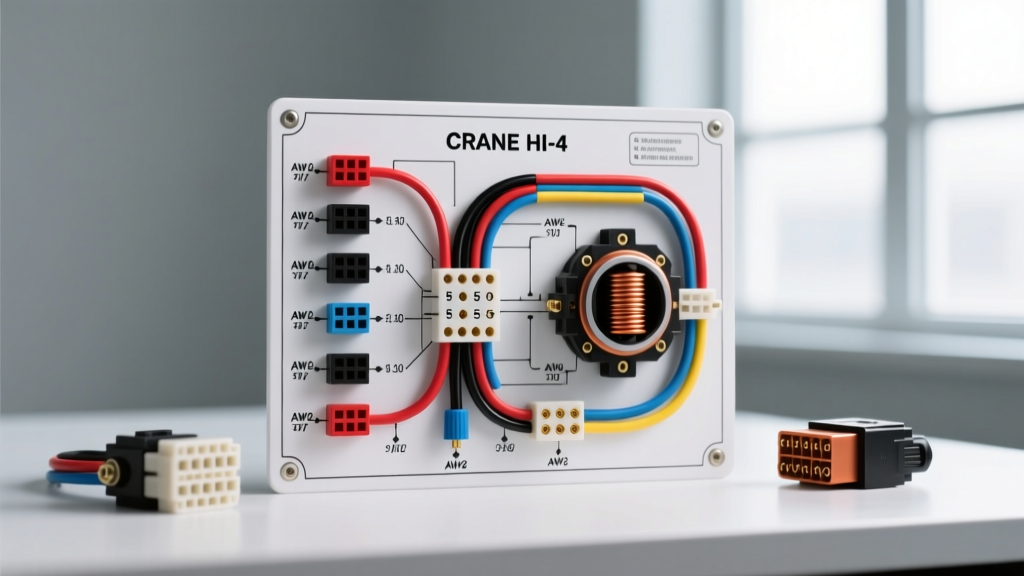
Crane HI-4 Capacitive Discharge Ignition: System Overview
The Crane HI-4 (and its subsequent HI-4S and HI-4E variants) remains one of the most robust capacitive discharge (CD) ignition modules ever engineered for automotive and motorcycle applications. Unlike traditional inductive ignition systems that rely on the slow collapse of a magnetic field, the HI-4 stores high-voltage energy in a capacitor and dumps it into the ignition coil in a matter of microseconds. This results in a significantly hotter, longer-duration spark capable of igniting lean air-fuel mixtures and resisting cylinder pressure blowout in high-compression or forced-induction engines.
However, the extreme current dump and high-frequency switching of the HI-4 module demand precise wiring execution. An improper crane hi 4 ignition wiring diagram implementation will lead to catastrophic module failure, phantom misfires, or alternator diode burnout. This technical specification reference details the exact wire color codes, AWG requirements, pinout configurations, and electromagnetic interference (EMI) mitigation strategies required for a flawless installation.
Core Wiring Harness & Color Code Specifications
The standard Crane HI-4 harness utilizes a multi-conductor loom. Adhering to SAE International J1128 standards for low-tension primary cables, wire gauge selection is critical to handle the transient current spikes, which can exceed 20 amps for fractions of a millisecond during the capacitor discharge phase.
| Wire Color | Function / Circuit | Min. AWG | Terminal / Connector Spec | Connection Destination |
|---|---|---|---|---|
| Red | +12V Switched Ignition | 12 AWG | Weather-Pack / Ring Terminal | Ignition Switch 'Run' Post (Post-Ballast) |
| Black | System Ground (-12V) | 12 AWG | Star-Washer Ring Terminal | Dedicated Chassis Ground or Battery (-) |
| White | Points Trigger / Tach Out | 18 AWG | Spade / Bullet Connector | Distributor Points Arm or Tachometer Signal |
| Violet | Magnetic Pickup (+) | 18 AWG | Weather-Pack Pin | Distributor Mag Pickup (+) Terminal |
| Green | Magnetic Pickup (-) | 18 AWG | Weather-Pack Pin | Distributor Mag Pickup (-) Terminal |
| Orange | Coil Primary (+) | 14 AWG | Coil Ring Terminal | Ignition Coil Positive (+) Terminal |
| Yellow | Coil Primary (-) | 14 AWG | Coil Ring Terminal | Ignition Coil Negative (-) Terminal |
Grounding Protocol: The Black Wire Imperative
The most common cause of HI-4 module failure is improper grounding of the Black wire. Because a CD ignition relies on a massive, instantaneous current dump, grounding the module to the engine block, intake manifold, or cylinder head introduces variable resistance and voltage bounce. The Black wire must be terminated using a star washer directly to bare, unpainted chassis metal or routed directly to the battery negative terminal. Applying dielectric grease to the ring terminal post after torquing to 15 ft-lbs prevents galvanic corrosion that degrades the ground path over time.
Trigger Circuit Configurations: Points vs. Magnetic Pickup
The HI-4 module is versatile, supporting both mechanical breaker points and magnetic reluctance pickups. The wiring topology changes depending on your distributor configuration.
Configuration A: Mechanical Points Trigger
When utilizing the factory distributor points as a trigger switch, the White wire is connected to the distributor side of the points. The points act as a simple switch to ground. When the points are closed, the White wire sees ground, and the module's internal logic charges the capacitor. When the points open, the ground is broken, triggering the Silicon Controlled Rectifier (SCR) to dump the stored energy into the coil. Note: The factory condenser must be completely removed from the distributor to prevent signal degradation and false triggering.
Configuration B: Magnetic Pickup Trigger
For aftermarket distributors (such as early Crane or Mallory magnetic units), the Violet and Green wires are used. Polarity is critical. If the engine backfires or timing advances erratically under load, the magnetic pickup polarity is reversed. Swap the Violet and Green wires at the distributor connector to correct the phase. Do not use shielded cable extensions for the magnetic pickup unless the shield is grounded at the module end only, to avoid creating a Faraday cage that traps alternator RFI.
Coil Selection and Primary Resistance Specifications
Capacitive discharge ignitions are fundamentally incompatible with standard high-resistance inductive coils. Connecting an HI-4 to a stock 1.5-ohm canister coil will cause the internal switching transistors to overheat and fail. You must use a low-resistance, high-turn-ratio coil specifically designed for CD systems.
| Coil Parameter | Required Specification for HI-4 | Failure Symptom if Out of Spec |
|---|---|---|
| Primary Resistance | 0.2 Ω to 0.5 Ω | Module overheating, burnt SCR gate, melted harness |
| Secondary Resistance | 3,000 Ω to 5,000 Ω | Weak spark, high-RPM misfire |
| Inductance | < 4.0 mH | Slow spark rise time, cylinder blowout under boost |
| Core Type | E-Core or Low-Inductance Canister | Saturation limits reached prematurely |
The Ballast Resistor Bypass
Classic vehicles equipped with points ignitions utilize a ballast resistor wire (typically 1.8 Ω) to reduce voltage to the coil during normal running, protecting the points from arcing. The HI-4 Red wire requires a full, unimpeded 12V+ during both 'Run' and 'Start' cranking phases. You must bypass the factory ballast resistor wire. Connect the Red wire to the ignition switch output, and run a secondary 12 AWG wire from the starter solenoid 'I' (Ignition) terminal to the Red wire. This ensures the module receives full battery voltage during cranking, when system voltage can drop to 9.5V.
EMI Suppression and Spark Plug Wire Routing
The rapid voltage rise time (dV/dt) of the HI-4's capacitor discharge generates severe Radio Frequency Interference (RFI). If this electromagnetic noise enters the trigger circuit (White, Violet, or Green wires), the module will interpret it as a false trigger signal, resulting in multiple sparks per cycle or severe backfiring.
- Spark Plug Wires: You must use spiral-core (suppression) spark plug wires, such as Taylor Spiro-Pro or MSD Super Conductor. Never use solid copper-core wires, as they act as antennas that broadcast RFI directly into the HI-4 harness.
- Harness Routing: The Orange and Yellow coil wires must be routed at least 4 inches away from the trigger wires (White/Violet/Green). Never bundle the coil wires and trigger wires in the same loom or zip-tie them together.
- Alternator Clearance: Route the main harness away from the alternator stator housing and voltage regulator to avoid induction from the AC ripple.
Diagnostic Decision Tree: Troubleshooting the HI-4
When diagnosing a no-spark condition, rely on a digital multimeter (DMM) and follow this structured diagnostic path. For deeper module-level diagnostics, refer to the Holley/MSD Technical Documentation Archive, which maintains legacy Crane Cams schematics.
- Verify Power & Ground: Set DMM to DC Volts. Probe Red wire to Black wire with ignition ON. Reading must be >11.8V. If <10.5V, trace for ballast resistor interference or corroded ignition switch contacts.
- Verify Coil Primary Resistance: Disconnect Orange and Yellow wires. Measure resistance across the coil's (+) and (-) posts. If reading is >0.8 Ω, the coil is incompatible or internally damaged. Replace with a CD-specific coil.
- Test the Trigger Signal (Points): Connect DMM to Ohms. Probe White wire to ground. Rotate engine by hand. Resistance should fluctuate between 0 Ω (points closed) and Infinite/Open (points open). If resistance remains >2 Ω when closed, points are oxidized or the condenser was left installed.
- Test the Trigger Signal (Magnetic): Set DMM to AC Volts. Probe Violet and Green wires at the distributor while cranking the engine. A healthy magnetic pickup will generate 1.5V to 3.0V AC. If 0V, check the air gap between the reluctor and pickup (spec: 0.015' - 0.025').
- Module Bypass Test: With ignition ON, momentarily tap the White wire to ground and pull it away. The coil should arc. If the coil arcs during this manual trigger test but not while the engine is running, the module is functional, and the fault lies entirely within the distributor trigger mechanism.
Terminal Crimping and Connector Best Practices
According to AutoShop 101 Ignition System Fundamentals, high-voltage automotive circuits demand superior mechanical connections. Soldering the Orange and Yellow coil wires directly to the coil posts is prohibited; the high heat from the coil terminals can melt the solder, causing an open circuit. Instead, use closed-barrel, nylon-insulated ring terminals crimped with a ratcheting crimper. Perform a 40-lb pull-test on all 12 AWG power connections to ensure the copper strands are properly swaged and will not vibrate loose under engine harmonics.