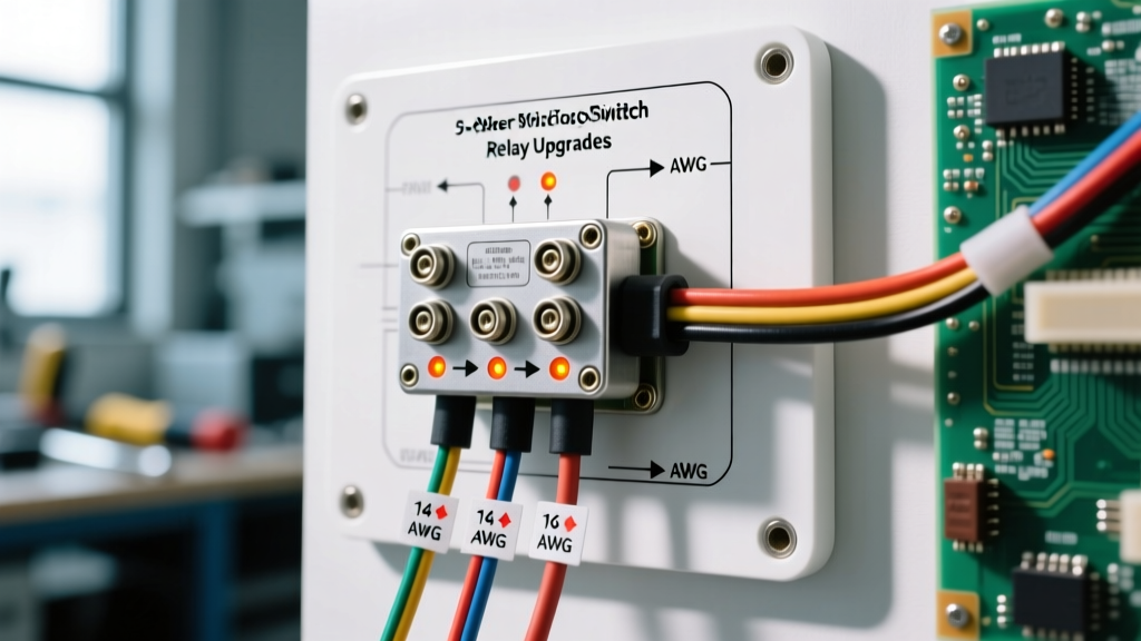
The Anatomy of an Automotive 5-Pin Rocker Switch
When executing an upgrade and modification project on a truck, Jeep, or overland SUV, adding auxiliary lighting, air compressors, or winch controls requires a reliable user interface. The industry standard for these modifications is the 5-pin SPST (Single Pole, Single Throw) rocker switch with dual LED illumination. While these switches are rated for 20A to 30A on paper, running high-draw inductive loads directly through the switch contacts is a recipe for melted housings and electrical fires. To build a professional-grade, fail-safe auxiliary circuit, you must integrate a Bosch-style automotive relay into your wiring diagram for rocker switch setups.
This guide provides the exact pinout configurations, wire gauge calculations, and step-by-step relay integration techniques required for a durable 12V DC modification. Whether you are wiring a 40-inch LED light bar on a Ford F-150 or an onboard air system on a Jeep Wrangler, understanding the micro-architecture of your switch and relay is non-negotiable.
Standard 5-Pin SPST Pinout Configuration
The most common 5-pin rocker switches (such as those following Carling V-Series or standard Nilight/Blue Sea footprints) utilize a specific terminal layout. Misidentifying these pins is the leading cause of short circuits and blown illumination LEDs during dash pod installations.
| Pin Number | Terminal Label | Function & Connection | Wire Color Recommendation |
|---|---|---|---|
| Pin 1 | +12V Illumination | Trigger for top LED (connects to dash/headlight circuit) | Blue w/ White Stripe |
| Pin 2 | +12V Source | Main power input from battery or fused bus bar | Red (12 AWG or 14 AWG) |
| Pin 3 | Load Output | Switched output to Relay Coil (Pin 86) | Yellow (16 AWG) |
| Pin 4 | Ground (LED 1) | Ground for illumination circuit | Black (16 AWG) |
| Pin 5 | Ground (LED 2) | Secondary ground (jumper to Pin 4) | Black (16 AWG) |
Why Direct Wiring Fails: The Relay Upgrade
Many amateur modders wire the load directly to Pin 3 of the rocker switch. While a 20A switch can theoretically handle a 15A light bar, it cannot handle the inrush current of inductive loads like air compressors or winch solenoids. Furthermore, running 14 AWG or 12 AWG power wires through the cabin and into a dash-mounted switch creates a massive clutter hazard and increases the risk of a dead short if the wire chafes against the steering column.
By utilizing a wiring diagram for rocker switch relay integration, the switch only carries the minimal current required to energize the relay coil (typically less than 150mA). The heavy current (30A+) is routed directly from the battery to the relay, and then to the accessory, completely bypassing the cabin.
Bosch-Style 4-Pin Relay Integration
A standard ISO mini relay (Bosch-style) features four primary pins:
- Pin 30 (Common): +12V from the battery (must be fused within 18 inches of the battery terminal).
- Pin 87 (Normally Open): Output to the auxiliary accessory (e.g., LED light bar positive).
- Pin 86 (Coil +): Receives the switched 12V signal from Rocker Switch Pin 3.
- Pin 85 (Coil -): Ground for the relay coil.
Inductive Kickback and Flyback Diodes
One of the most overlooked aspects of automotive relay wiring is inductive kickback. When the rocker switch is turned off, the magnetic field in the relay coil collapses, sending a high-voltage spike backward through the circuit. Over time, this spike will fry the internal resistors of your rocker switch's LED illumination. To prevent this, professional wiring diagrams incorporate a flyback diode (such as a 1N4001) across the relay coil pins (85 and 86), with the cathode (striped end) facing Pin 86. This provides a safe path for the voltage spike to dissipate, extending the life of your switch and dash electronics.
AWG Wire Sizing and Overcurrent Protection Chart
Selecting the correct wire gauge is critical to preventing voltage drop and thermal runaway. The following chart is based on SAE J1128 Low Tension Cable Standards and assumes a 12V system with a maximum acceptable voltage drop of 3% over a 15-foot total circuit length (power + ground).
| Max Continuous Load | Recommended Wire (AWG) | Fuse / Breaker Size | Relay Rating Required |
|---|---|---|---|
| 10 Amps | 16 AWG | 15A ATO | 20A Mini Relay |
| 20 Amps | 14 AWG | 25A ATO | 30A Mini Relay |
| 30 Amps | 10 AWG | 40A Maxi | 40A Standard Relay |
| 40 Amps | 8 AWG | 50A Maxi | 50A Heavy Duty Relay |
Note: Always size your fuse to protect the wire, not the load. For comprehensive circuit protection strategies, refer to the Blue Sea Systems Circuit Protection Guide.
Step-by-Step Rocker Switch and Relay Wiring Project
- Plan the Power Feed: Run your main power wire (e.g., 10 AWG for a 30A light bar) from the auxiliary battery or main battery positive terminal. Install an inline Maxi-fuse holder within 18 inches of the battery. Route the wire through the firewall using a rubber grommet and apply silicone dielectric grease to prevent water ingress into the cabin.
- Wire the Relay: Crimp a closed-barrel ring terminal onto the Pin 30 wire and connect it to the fused power feed. Connect Pin 87 to the positive wire of your auxiliary accessory. Connect Pin 85 to a clean, bare-metal chassis ground using a star washer to bite through the paint and ensure a low-resistance path.
- Prepare the Rocker Switch Harness: Using 16 AWG primary wire, crimp female spade terminals onto your switch wires. Connect Pin 2 to a switched 12V source (like the cigarette lighter circuit or an upfitter switch block) so the relay only receives power when the ignition is on. Connect Pin 3 to Relay Pin 86.
- Wire the Illumination: Connect Pin 1 to your dash illumination circuit (often the headlight switch output) so the rocker switch LED dims with your factory dash lights. Connect Pins 4 and 5 together, and route them to a dedicated cabin ground bus bar.
- Seal and Protect: Do not rely on electrical tape. Use adhesive-lined polyolefin heat shrink tubing on all crimp connections. The inner adhesive melts and seals the wire strands, preventing galvanic corrosion and moisture wicking, which is vital for off-road and marine environments.
Troubleshooting Common Mod Failures
Even with a perfect wiring diagram for rocker switch setups, environmental factors and installation errors can cause issues. Use this decision tree to diagnose problems:
- Symptom: The rocker switch housing is hot to the touch.
Cause: The load is wired directly through the switch, exceeding its continuous amperage rating, or the wire gauge is too small, causing resistance heat.
Fix: Rewrite the circuit to use a relay. Ensure the switch is only triggering the relay coil. - Symptom: The rocker switch LED flickers or glows dimly when turned OFF.
Cause: Backfeed voltage from a shared ground circuit, or a modern vehicle's CAN-bus system sending a low-voltage pulse to check for blown bulbs.
Fix: Isolate the switch ground to a dedicated chassis point. If CAN-bus interference is the culprit, install a 1N4001 diode on the illumination trigger wire to block reverse voltage. - Symptom: Relay clicks audibly, but the accessory receives no power.
Cause: Pitted or corroded contacts inside the relay on Pin 30/87, or a blown main fuse.
Fix: Test voltage at Pin 87 with a multimeter while the switch is engaged. If voltage is absent but the coil clicks, replace the relay. Always use sealed, weather-pack relays for under-hood or under-chassis mounting.
Final Torque and Inspection Specifications
Before closing up your dash pod or engine bay, verify all terminal connections. Battery terminal ring lugs should be torqued to manufacturer specifications (typically 8-12 Nm for standard M8 terminal posts). Ground points must be sanded down to bare, shiny metal, secured with a serrated flange nut or star washer, and coated with battery terminal protector spray to halt oxidation. A properly executed 5-pin rocker switch and relay upgrade will provide years of reliable, weather-proof operation for your vehicle's auxiliary systems.