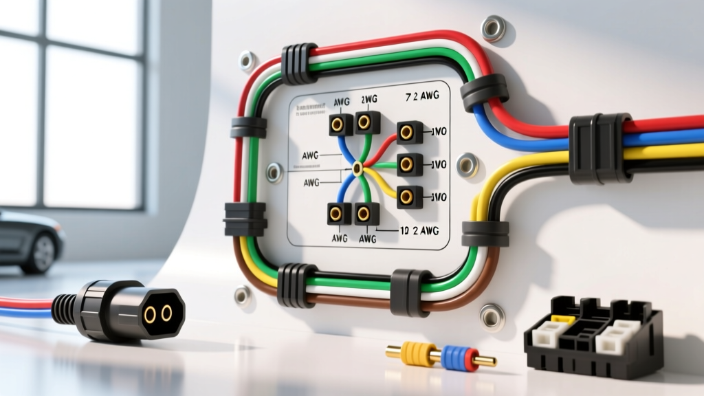
The Critical Role of the 7-Way RV Blade Connector
When towing a travel trailer, fifth wheel, or heavy-duty camper, the electrical connection between your tow vehicle and the RV is the lifeline for both safety and functionality. While a standard 4-way flat connector handles basic lighting for small utility trailers, larger RVs require the 7-way RV blade connector to support electric trailer brakes, auxiliary 12V power for interior systems, and reverse lockout solenoids. Unfortunately, misinterpreting an RV plug wiring diagram trailer schematic is one of the most common causes of roadside electrical fires and catastrophic brake failures.
As an automotive electrical specialist, I frequently diagnose trailers that have suffered melted harnesses, locked-up brake hubs, and blown tow vehicle alternators due to improper DIY wiring. This guide breaks down the exact RVIA (Recreational Vehicle Industry Association) pinout standards, highlights the most dangerous wiring mistakes, and provides actionable safety warnings to ensure your rig is road-legal and safe.
Standard 7-Way RVIA Pinout & Wire Gauge Specifications
Before cutting or stripping any wire, you must understand the industry-standard color codes and amperage requirements. The SAE International J286 Standard and RVIA guidelines dictate the following configuration for the 7-way RV blade connector (viewed from the wiring side of the plug):
| Pin Position | Function | Standard Wire Color | Minimum AWG Size | Max Continuous Amperage |
|---|---|---|---|---|
| Pin 1 (Center) | Chassis Ground | White | 10 AWG (8 AWG Preferred) | 40A |
| Pin 2 (Top Right) | Electric Brakes | Blue | 10 AWG | 15A (Total for 4 brakes) |
| Pin 3 (Bottom Right) | Tail / Running Lights | Brown | 12 AWG | 10A |
| Pin 4 (Top Left) | Auxiliary 12V Power | Black | 10 AWG | 30A |
| Pin 5 (Bottom Left) | Right Turn / Stop | Green | 12 AWG | 10A |
| Pin 6 (Center Left) | Left Turn / Stop | Yellow | 12 AWG | 10A |
| Pin 7 (Bottom Center) | Reverse Lights / Backup | Red (or Purple) | 12 AWG | 10A |
Note: Always verify your specific trailer manufacturer's schematic, as some older or custom European imports may deviate from the North American RVIA standard.
5 Fatal Wiring Mistakes in RV Trailer Harnesses
Mistake 1: Swapping Pin 2 (Electric Brakes) and Pin 4 (Auxiliary 12V)
This is the most destructive error found in DIY trailer wiring. Pin 2 (Blue) carries the modulated voltage from the tow vehicle's brake controller to the trailer's electric brake magnets. Pin 4 (Black) provides a constant 12V feed from the tow vehicle's battery to charge the trailer's house battery or run interior 12V appliances.
The Failure Mode: If these two pins are swapped at the plug, the moment you connect the trailer, a full, unmodulated 12 volts is sent directly to the electric brake magnets. According to Tekonsha brake controller engineering specs, a standard 10-inch or 12-inch brake magnet draws between 3.0 and 3.5 amps at 12V. A dual-axle RV (4 magnets) will pull 12 to 14 amps continuously. Because the brake controller is bypassed, the magnets will remain fully engaged while driving, generating immense friction and heat. Within 10 to 15 miles, the brake hubs will overheat, melting the bearing grease, destroying the wheel bearings, and potentially igniting a tire fire.
Mistake 2: Undersizing the Ground Wire (Pin 1)
Many DIYers treat the white ground wire as an afterthought, using whatever scrap 14 AWG or 16 AWG wire is left over from the lighting circuits. This violates basic electrical physics.
The Failure Mode: The ground wire carries the return current for every single active circuit on the trailer. If you are running the tail lights (5A), the interior 12V charging circuit (15A), and the refrigerator heating element, the ground wire may be carrying 20+ amps. Using an undersized 14 AWG ground wire over a 30-foot trailer run creates severe voltage drop. This results in dim exterior lights, erratic brake controller behavior, and 'backfeeding,' where current seeks an alternative path to ground through the trailer hitch ball or safety chains, causing severe galvanic corrosion and intermittent electrical shorts.
Mistake 3: Using THHN Household Wire Instead of GXL/TXL
Hardware store THHN or Romex wire is designed for climate-controlled indoor environments. Automotive and RV environments require cross-linked polyethylene insulation, specifically GXL or TXL wire.
The Failure Mode: THHN insulation becomes brittle when exposed to UV light, road salt, and the extreme temperature fluctuations of an undercarriage environment. Furthermore, THHN is stranded poorly for vibration. Over a single season of towing, the vibration will cause the copper strands inside a THHN wire to fracture, leading to high-resistance arcing inside the wire loom—a primary cause of hidden trailer fires.
Mistake 4: Taping Splices with Vinyl Electrical Tape
Vinyl electrical tape is for temporary bundling, not environmental sealing. Underneath an RV, road spray, mud, and summer asphalt heat (often exceeding 140°F near the axles) will cause vinyl tape adhesive to melt and slide off the wire.
The Fix: Use only marine-grade, heat-shrink butt connectors with an internal polyolefin lining. When heated, the polyolefin melts and seals the copper crimp, making it completely waterproof. For chassis grounding points, always use a ring terminal with a star washer to bite through the paint and bare metal, sealed with dielectric grease.
Mistake 5: Misunderstanding the Breakaway Switch Circuit
The breakaway switch is a critical safety device that applies full trailer braking power if the trailer accidentally detaches from the tow vehicle. A common mistake is wiring the breakaway switch to the 12V Auxiliary pin (Pin 4) of the 7-way plug.
The Failure Mode: If the trailer unhitches, the 7-way plug is ripped out of the socket. Pin 4 instantly loses power. If your breakaway switch relies on Pin 4, it will not activate, and the detached trailer will roll away with zero braking force. The breakaway switch must be wired directly to the trailer's onboard 12V battery with a dedicated inline fuse, completely independent of the tow vehicle's 7-way plug.
Safety Warnings: Fire and Brake Failure Hazards
- Alternator Overload: Modern tow vehicles use smart alternators. If your RV plug wiring diagram relies on the tow vehicle's alternator to charge a deeply depleted 100Ah trailer battery via a long, undersized wire, you can overheat and destroy the tow vehicle's alternator diode bridge. Always use a DC-to-DC battery charger in the trailer to manage charging current safely.
- Short Circuit Protection: The 12V Auxiliary (Black) and Electric Brake (Blue) circuits must be protected by a 30A and 20A circuit breaker, respectively, mounted within 18 inches of the trailer's main battery or power distribution block. Never rely solely on the tow vehicle's fuses to protect the trailer's internal wiring.
- Corrosion at the Plug: Apply a high-quality silicone dielectric grease to the pins of the 7-way plug before every trip. Green copper oxide buildup increases resistance, which translates to voltage drop at the brake magnets, resulting in weak braking performance and trailer sway on downhill grades.
Troubleshooting Decision Tree: Trailer Electrical Faults
Use this structured diagnostic tree when your trailer exhibits abnormal electrical behavior after modifying or repairing the 7-way harness.
- Symptom: Trailer brakes lock up instantly when plugged in, without pressing the brake pedal.
- Cause: 12V Auxiliary (Pin 4) and Electric Brake (Pin 2) wires are swapped.
- Fix: Disconnect immediately. Rewire the plug to RVIA standard. Inspect brake magnets for heat damage and replace if the internal coil is melted.
- Symptom: Left turn signal on trailer blinks rapidly, but tail lights also flash in unison.
- Cause: High resistance or open circuit on the White Ground wire (Pin 1). Current is backfeeding through the tail light circuit to find a ground.
- Fix: Clean the main chassis ground point to bare metal. Upgrade ground wire to 8 AWG and verify continuity from the plug to the trailer frame.
- Symptom: Tow vehicle's brake controller displays 'C' or 'OL' (Overload) error code.
- Cause: Short to ground on the Blue brake wire, or a seized brake magnet.
- Fix: Disconnect the 7-way plug. Use a multimeter to measure resistance between Pin 2 and Pin 1 on the trailer side. A normal dual-axle trailer should read between 3.0 and 4.0 ohms. A reading of 0.0 ohms indicates a chafed wire shorting against the frame.
Final Recommendations for RV Wiring Integrity
Properly executing an RV plug wiring diagram trailer project requires adherence to Recreational Vehicle Industry Association (RVIA) standards and a respect for the harsh undercarriage environment. Always invest in premium GXL cross-linked wire, use polyolefin heat-shrink terminations, and double-check your pinout with a digital multimeter before connecting the trailer to your tow vehicle. By avoiding these common mistakes, you ensure that your trailer's lighting, braking, and charging systems operate reliably for thousands of miles of safe towing.