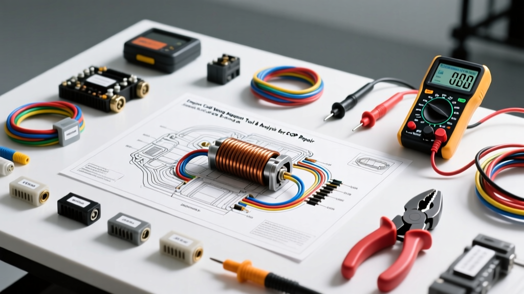
The True Cost of Ignition Diagnostics: Beyond the Engine Coil Wiring Diagram
When a modern Coil-On-Plug (COP) ignition system throws a P0351-P0358 diagnostic trouble code, the immediate instinct is to replace the suspected coil. However, throwing $60 OEM coils at a misfire without consulting an engine coil wiring diagram is a costly mistake. As an automotive electrical specialist, I see countless enthusiasts and junior technicians misdiagnose ignition faults because they lack the specific diagnostic tools required to test the circuits mapped out in the factory schematic.
Understanding an engine coil wiring diagram is only 20% of the battle. The remaining 80% relies on having the correct equipment to verify the power, ground, and pulse-width modulated (PWM) trigger signals, as well as the budget to execute proper OEM-spec wiring repairs. This guide breaks down the exact tool requirements, associated costs, and technical specifications needed to properly diagnose and repair COP ignition circuits, using the ubiquitous GM Gen IV LS3 3-pin COP system as our benchmark.
Decoding the Engine Coil Wiring Diagram: What You Are Actually Testing
Before spending money on tools, you must understand what the engine coil wiring diagram is asking you to verify. A standard 3-wire COP circuit (common on GM LS, LT, and many Toyota engines) requires three distinct electrical paths to function:
- Ignition Feed (B+): A 12V reference voltage supplied by the ignition relay, typically active only in the 'Run' and 'Start' key positions.
- Low-Reference Ground: A dedicated chassis or engine block ground path that completes the primary coil circuit.
- PCM Trigger (IC Signal): A 5V square-wave signal from the Powertrain Control Module (PCM) that dictates dwell time and fires the coil.
If your engine coil wiring diagram shows a 4-pin connector (common on Ford Coyote 5.0L and Chrysler HEMI applications), a fourth wire is added for a shield ground or a coil sense/feedback circuit, allowing the PCM to monitor actual coil charging current. Testing these signals requires vastly different tools, which directly impacts your diagnostic budget.
Essential Diagnostic Tools & Cost Breakdown
Interpreting the wiring schematic requires translating paper diagrams into real-world voltage and resistance measurements. Below is the cost analysis of the tools required to properly test COP circuits without causing collateral damage to the PCM.
| Diagnostic Tool | Application for Coil Diagram | Est. Cost | Risk Level if Misused |
|---|---|---|---|
| Digital Multimeter (DMM) | Testing B+ voltage, ground continuity, and wire resistance. | $150 - $400 | Low |
| Automotive Logic Probe | Verifying presence of PCM trigger signal without loading the circuit. | $40 - $80 | Medium |
| High-Impedance LED Tester | Quick visual check for B+ and Ground. | $15 - $25 | High (Can draw excess current) |
| 2-Channel Automotive Oscilloscope | Visualizing dwell time, current ramping, and 5V PWM trigger integrity. | $450 - $1,200 | Very Low |
| OEM Breakout Box / Harness | Back-probing PCM connectors safely to read trigger signals at the source. | $120 - $250 | Low |
Tier 1: The Budget Approach (Multimeter & Test Light)
A high-quality Digital Multimeter (like the Fluke 88V, approx. $380) is the bare minimum requirement. According to SAE J1113 standards for automotive electromagnetic compatibility, modern ignition systems generate massive voltage spikes. A cheap $20 hardware store multimeter lacks the internal shielding and transient protection to survive a COP primary ring event, often resulting in a blown internal fuse or fried PCB.
Warning: Never use a standard incandescent test light to probe the PCM trigger wire identified on your engine coil wiring diagram. An incandescent bulb draws 1.5 to 3 amps. The PCM's internal ignition driver transistor is typically rated for a maximum of 4 amps across all cylinders combined. Probing a single trigger wire with a test light will instantly short the driver to ground through the bulb's low resistance, permanently destroying the PCM (a $400+ replacement cost).
Tier 2: The Professional Approach (Oscilloscope)
To truly validate the data in an engine coil wiring diagram, an automotive oscilloscope (such as the PicoScope 4225A, approx. $550) is mandatory. A multimeter averages voltage over time, meaning it will read a 5V PWM trigger signal as a confusing 2.5V. An oscilloscope graphs voltage against time, allowing you to see the exact millisecond the PCM pulls the signal low to begin coil dwell, and the inductive kickback spike (often 300V-400V) when the coil fires. For deep-dive waveform analysis, the Pico Technology Automotive Oscilloscope Library provides industry-standard reference waveforms for ignition current ramping.
Vehicle-Specific Wiring Specs: GM Gen IV LS3 COP Pinout
To illustrate the technical depth required, let us analyze the specific wiring parameters for the GM Gen IV LS3 (2008-2013 Corvette/Camaro) 3-pin COP system. When consulting the GM Technical Information System (TIS) engine coil wiring diagram, you will encounter a Delphi Metri-Pack 280 series 3-way connector.
| Pin | Function | OEM Wire Color | AWG Size | Expected Voltage / Spec |
|---|---|---|---|---|
| A | Low Reference Ground | Black (BK) | 18 AWG | < 0.2 Ohms to engine block |
| B | IC Control (PCM Trigger) | Gray (GY) | 20 AWG | 5V Square Wave (0V-5V) |
| C | Ignition 1 Feed (B+) | Pink (PK) | 16 AWG | 12.6V (Key On/Run) |
Wire Gauge and Voltage Drop Analysis
Notice the variance in AWG sizes on the diagram. The Ignition Feed (Pin C) is 16 AWG because the primary coil winding draws between 6 to 11 amps during the dwell phase. The PCM Trigger (Pin B) is 20 AWG because it only carries a low-current 5V logic signal. If you are repairing a melted harness, substituting the 16 AWG power wire with 20 AWG wire will result in severe voltage drop under high RPM dwell conditions, leading to weak sparks and high-speed misfires.
Real-World Failure Modes & Repair Cost Analysis
Once your tools and wiring diagram have isolated the fault to a wiring issue, the repair strategy dictates your final cost. Ignition harnesses frequently fail due to heat degradation, vibration-induced wire chafing near the valve covers, or terminal corrosion.
Scenario A: Terminal Corrosion and Fretting
Vibration causes micro-movements between the male coil tab and the female harness terminal, leading to fretting corrosion. This increases resistance, causing the PCM trigger signal to degrade.
- The 'Hack' Fix ($0): Bending the terminals with a pick tool. Result: Fails in 300 miles.
- The Proper Fix ($25 - $45): Cutting the harness back 3 inches and splicing in a new OEM AC Delco pigtail (Part #PT2834). This requires a proper Delphi Metri-Pack 280 crimping tool (approx. $60 investment) and adhesive-lined marine heat shrink ($8). Total repair cost: ~$35.
Scenario B: Chafed PCM Trigger Wire
The 20 AWG Gray trigger wire rubs against the aluminum intake manifold, shorting the 5V signal to ground. This causes a dead cylinder and sets a P035X code.
- The 'Hack' Fix ($2): Wrapping the exposed copper in electrical tape. Result: Tape melts off the hot intake, short returns, potential PCM damage.
- The Proper Fix ($12): Splicing in a new section of 20 AWG GXL (Cross-linked) automotive wire using a butt-seal crimp, followed by split-loom corrugated tubing and Tesa 51036 PET cloth harness tape to secure it away from the manifold. Total repair cost: ~$12.
Summary: The ROI of Proper Diagnostic Tooling
Reading an engine coil wiring diagram without the tools to verify its data is like reading a map without a compass. While a basic multimeter ($150+) and OEM pigtails ($30) will solve 80% of COP wiring faults, investing in an automotive oscilloscope ($500+) elevates your diagnostic capability from 'guessing' to 'verifying'. By understanding the specific AWG requirements, pin configurations, and Delphi connector specs outlined in the factory diagrams, you avoid the catastrophic costs of fried PCMs and misdiagnosed components, ensuring a permanent, OEM-quality repair.