Decoding the 200 Amp Meter Base Wiring Diagram PDF for Automotive Use
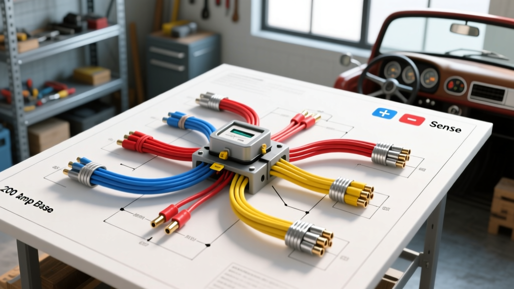
When upfitters, expedition vehicle builders, and EV conversion specialists search for a 200 amp meter base wiring diagram pdf, they are typically bridging the gap between heavy-duty residential-style busbars and automotive DC shunt monitoring. In the automotive and marine sectors, a "meter base" rarely refers to an AC utility enclosure. Instead, it refers to the main DC distribution busbar housing or the physical shunt enclosure used to monitor high-amperage current flow in 12V and 24V systems. Whether you are wiring a dual-alternator Ford F-350 6.7L Powerstroke for a massive winch setup, or building a 24V lithium bank in a Ram 3500 expedition camper, accurate DC metering is non-negotiable.
However, adapting high-current schematics to the harsh, vibration-heavy environment of a heavy-duty truck introduces severe risks. A 200-amp continuous DC load at 12V pushes 2,400 watts of power. A single wiring mistake won't just blow a fuse; it can melt 2/0 AWG copper, ignite chassis insulation, or send voltage spikes back into your vehicle's PCM/ECU. This guide breaks down the critical safety warnings and common wiring mistakes associated with high-amperage DC meter bases in automotive applications.
Critical Safety Warnings Before You Wire
The Arc Flash and Thermal Runaway Reality
Unlike AC systems, DC current does not have a zero-crossing point, meaning a DC arc will sustain itself until the metal vaporizes or the circuit is physically broken. If a 2/0 AWG main battery cable shorts against the chassis before the main overcurrent protection device, the vehicle's battery bank will dump thousands of cold cranking amps (CCA) into the short in milliseconds. Standard ANL fuses are often too slow to interrupt a dead short on a massive lithium or dual-AGM battery bank. You must install a Class T fuse (rated for 10,000 AIC - Ampere Interrupting Capacity) within 7 inches of the battery positive terminal before routing any cables to your meter base or shunt.
Isolation from the Chassis Ground
A fundamental rule of high-precision DC metering is that the shunt must be the only path to the battery negative. The meter base housing and the shunt's load-side negative busbar must be completely isolated from the vehicle's steel chassis. If the meter base is bolted directly to bare metal without dielectric isolation pads, current will bypass the shunt through the chassis, rendering your amp-hour readings useless and potentially electrifying the truck frame.
The 4 Most Common Wiring Mistakes (And How They Destroy ECUs)
Mistake 1: The "Sneak Path" Ground
The Error: Wiring auxiliary loads (like DC-DC chargers, inverter ground straps, or aftermarket lighting relays) to the battery-side of the shunt or directly to the chassis near the battery. The Consequence: The meter base cannot measure these loads. More dangerously, if the main battery negative cable corrodes or breaks, the return current for these auxiliary loads will seek a path through the vehicle's CAN-bus wiring harness and ECU ground pins, instantly frying the PCM.
Mistake 2: Alternator Ripple Interference on Sense Wires
The Error: Routing the shunt's low-voltage sense wires (usually an RJ12 or Molex connector carrying millivolt signals) parallel to the alternator's main positive output cable. The Consequence: Heavy-duty truck alternators (like the 220A+ units on modern Super Dutys) generate significant AC ripple. If unshielded sense wires run parallel to this high-current AC ripple, electromagnetic interference (EMI) induces a false voltage in the sense lines. Your battery monitor will display erratic, jumping amperage readings, causing automated battery isolators or BMS systems to prematurely disconnect the bank.
Mistake 3: Galvanic Corrosion at the Busbar
The Error: Bolting bare copper ring terminals directly to an aluminum meter base busbar without oxidation inhibitor. The Consequence: Aluminum and copper create a galvanic battery when exposed to underhood humidity and road salt. This creates aluminum oxide, a highly resistive insulator. Under a 200A load, this resistance generates massive heat, eventually melting the terminal and causing a fire. Always use tinned copper lugs and apply a dielectric antioxidant paste (like Noalox) to aluminum busbars.
Mistake 4: Undersizing the Main Cables
The Error: Using 1 AWG or 1/0 AWG wire for a 200A continuous load because it "fits the lug." The Consequence: According to SAE J1128 standards for low-tension primary cable, wire ampacity derates heavily in high-temperature engine bays. A 1/0 AWG wire rated for 150A in free air will overheat when bundled in a loom near a diesel exhaust manifold. You must use 2/0 AWG (00 AWG) fine-strand marine-grade wire for any 200A continuous automotive circuit.
Step-by-Step Installation Sequence for Heavy-Duty Trucks
- Disconnect and Isolate: Remove the negative battery cable first, then the positive. Cap the positive terminal with a rubber boot.
- Mount the Meter Base: Secure the DC shunt/meter base to a non-conductive surface (like a composite battery tray or using nylon isolation bushings). Ensure it is within 12 inches of the battery negative.
- Install Overcurrent Protection: Mount the Class T fuse on the positive side, within 7 inches of the battery post.
- Crimp and Seal: Use a 6-ton hydraulic crimper for all 2/0 AWG terminals. Seal the crimp barrel with 3:1 ratio adhesive-lined marine heat shrink to prevent acid vapor intrusion.
- Route Sense Wires: Run the meter's data/sense cables in a separate split-loom, at least 6 inches away from the alternator B+ terminal and ignition coils.
- Torque to Spec: Use a calibrated inch-pound torque wrench on all busbar hardware. (See chart below).
Technical Specifications and Torque Chart
Proper hardware torque is critical. Overtorqing can strip soft brass or aluminum threads on the meter base, while undertorquing allows micro-movements that lead to arcing under heavy vibration (e.g., off-road expedition driving). Refer to Blue Sea Systems hardware guidelines for marine and heavy-truck applications.
| Wire Gauge (AWG) | Stud Size | Terminal Type | Target Torque (in-lbs) | Max Continuous Ampacity (Engine Bay) |
|---|---|---|---|---|
| 2/0 AWG | 3/8" (M10) | Tinned Copper Ring | 240 - 275 in-lbs | 225 Amps |
| 1/0 AWG | 3/8" (M10) | Tinned Copper Ring | 240 - 275 in-lbs | 175 Amps |
| 2 AWG | 5/16" (M8) | Tinned Copper Ring | 120 - 140 in-lbs | 130 Amps |
| 18 AWG (Sense) | N/A (Molex/RJ12) | Shielded Twisted Pair | N/A (Click-Seated) | Signal Only (< 1A) |
Troubleshooting Voltage Drop and Shunt Drift
If your battery monitor or meter base display shows a discrepancy between the alternator output and the battery bank input, perform a voltage drop test across the shunt itself. A healthy 500A/50mV shunt should drop exactly 50 millivolts when 500 amps are flowing. If you measure a higher voltage drop across the physical connections of the meter base, you have a high-resistance joint caused by poor crimping, missing antioxidant paste, or undertorqued hardware.
Furthermore, if your meter shows negative amperage while the truck is off, check for a "sneak path" ground. Disconnect the main negative cable from the load-side of the shunt. If the vehicle still has power (e.g., the dome lights turn on or the ECU remains awake), you have a load grounded directly to the chassis, bypassing your meter base entirely. Trace and reroute all negative returns to the load-side busbar of the meter base to ensure 100% accurate amp-hour tracking and to protect your vehicle's sensitive CAN-bus network from ground-fault anomalies.