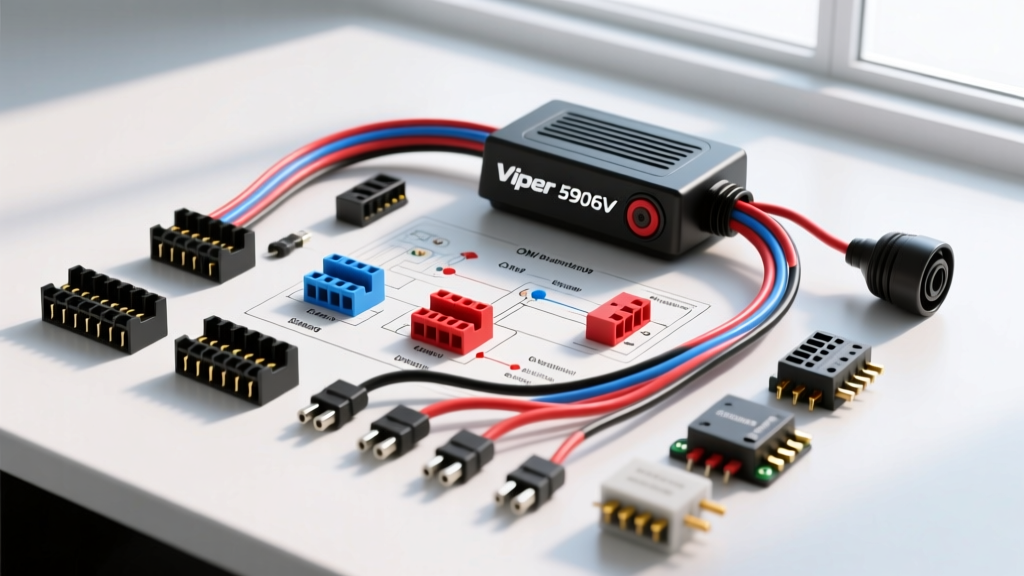
Introduction to the Viper 5906V Architecture
Integrating an advanced security and remote start system requires a precise understanding of both the aftermarket module and the vehicle's OEM electrical topology. This technical specification reference details the car alarm wiring diagram for the Viper 5906V platform, a flagship Directed Electronics module. Unlike basic siren-and-door-trigger setups, modern alarm integration relies heavily on Data-to-Data (D2D) CAN-bus communication, high-current relay logic, and multiplexed signal decoding. Improper harness termination or misidentification of OEM wire color codes can result in parasitic battery drains, ECU fault codes, or catastrophic short circuits. The following matrices and diagnostic protocols align with MECP Mobile Electronics Certification Program standards and SAE J1113 Electromagnetic Compatibility guidelines for automotive aftermarket electronics.
Primary 12-Pin Power and Ground Harness (H1)
The H1 harness handles the high-current distribution required for remote starting and system power. All high-current outputs are internally fused or rely on external inline ATC/ATO fuses. When routing these 10 AWG and 14 AWG wires, maintain a minimum 3-inch separation from OEM audio cables and high-voltage ignition coils to prevent Electromagnetic Interference (EMI).
| Pin | Wire Color | AWG | Function / Polarity | Integration Specification |
|---|---|---|---|---|
| 1 | RED | 10 AWG | (+) 12V Constant Input | Connect to battery positive via a 30A fuse within 12 inches of the terminal. |
| 2 | RED | 10 AWG | (+) 12V Constant Input | Secondary power feed for load balancing. Must be fused independently at 30A. |
| 3 | BLACK | 10 AWG | (-) Chassis Ground | Terminate to bare steel using an M6/M8 ring terminal. Torque to 10 Nm. Apply dielectric grease. |
| 4 | VIOLET | 14 AWG | (+) Starter Output | Feeds the starter kill relay coil (Pin 85). Outputs 12V only during remote start cranking. |
| 5 | YELLOW | 14 AWG | (+) Ignition 1 Input | Senses OEM ignition cylinder ON position. Draw is typically less than 5mA. |
| 6 | GREEN | 14 AWG | (+) Ignition 2 / ACC Input | Senses accessory circuit. Required for proper tachless or CAN-bus remote start handoff. |
| 7 | BLUE | 18 AWG | (+) Status Output | 500mA maximum. Outputs 12V when armed. Used to drive OEM horn or external LED indicators. |
| 8 | ORANGE | 18 AWG | (+) Accessory Output | 500mA maximum. Active during remote start to power OEM HVAC blower motors via external relay. |
| 9 | PINK | 14 AWG | (+) Ignition 1 Output | High current output to feed OEM ignition circuits during remote start sequence. |
| 10 | PINK/WHITE | 14 AWG | (+) Ignition 2 Output | Feeds secondary ignition/accessory circuits required by specific OEM ECM wake-up protocols. |
| 11 | ORANGE/WHITE | 14 AWG | (+) Accessory Output | High current output for OEM radio and infotainment wake-up during remote start. |
| 12 | VIOLET/WHITE | 14 AWG | (+) Starter Output | High current output to engage the OEM starter solenoid directly or via a heavy-duty isolation relay. |
24-Pin Door Lock and Security Input Harness (H2)
The H2 light-gauge harness manages sensor inputs, factory alarm integration, and low-current outputs. Modern vehicles rarely use simple discrete ground triggers for doors; instead, they utilize multiplexed resistor networks or direct CAN-bus messaging. Before splicing into any wire on this harness, verify the circuit topology using a digital multimeter (DMM) and an oscilloscope if dealing with LIN-bus or multiplexed signals. For comprehensive OEM wire color codes and bypass matrices, installers should consult Directed Electronics Technical Support and Wiring Matrices.
| Pin | Wire Color | Function | Multimeter Diagnostic Profile |
|---|---|---|---|
| 1 | GREEN | (-) Discrete Door Trigger | Tests 0.0 ohms to ground when door is open; infinite when closed. Common on pre-2005 vehicles. |
| 2 | VIOLET | (+) Discrete Door Trigger | Tests +12V when door is open; 0V when closed. Common on older Ford and Chrysler platforms. |
| 3 | BLUE | (-) Trunk / Hatch Trigger | Ground trigger. May require a 1N4001 diode to isolate from OEM dome light delay modules. |
| 4 | BLACK/WHITE | (-) Dome Light Supervision | 500mA ground output. Must be fused at 2A to prevent backfeeding and frying the alarm's internal transistor. |
| 5 | WHITE | (+/-) Selectable Parking Light | Jumper selectable on the module. Capable of driving OEM lighting control modules directly (max 10A). |
| 6 | BROWN | (+) Horn / Siren Output | Outputs +12V during trigger events. Use an external 30A relay if driving dual OEM high-dB snail horns. |
| 7 | LIGHT GREEN/BLACK | (-) Factory Alarm Disarm | Pulses ground to simulate the OEM key fob unlock button press on the door lock multiplex wire. |
| 8 | LIGHT GREEN | (-) Factory Alarm Arm | Pulses ground to simulate the OEM lock button press, ensuring the factory security system sets properly. |
OEM Multiplexed vs. Discrete Door Trigger Identification
A critical failure point in executing a car alarm wiring diagram is misidentifying multiplexed door triggers as discrete triggers. Connecting the GREEN (H2 Pin 1) wire to a multiplexed data line will not trigger the alarm and can potentially backfeed voltage into the vehicle's Body Control Module (BCM), causing localized network faults.
- Discrete Triggers: Operate on a simple binary state. A DMM will show a clean transition from 12V to 0V (or Ground to Open) with zero intermediate voltage steps.
- Multiplexed / Resistor Ladder Triggers: Common in GM and Toyota platforms. The door switch alters the resistance on a single 5V reference wire. When the door opens, the voltage may drop from 5.0V to 3.2V, then to 1.8V depending on which door is opened. The Viper 5906V requires a Digital Data Port (D2D) bypass module to translate these analog voltage steps into a digital CAN-bus message the alarm brain can understand.
- CAN-Bus Triggers: No physical trigger wire exists at the door jamb. The door latch microswitch sends a LIN-bus message to the door module, which translates it to a CAN-bus message on the high-speed network. Integration strictly requires a D2D interface module (e.g., Fortin EVO-ALL or idatalink Maestro) connected to the OBD2 CAN-H and CAN-L pins.
Starter Kill Relay Logic and Isolation
The VIOLET wire on the H1 harness does not carry the starter motor's cranking amperage (which can exceed 150A). It provides a low-current 12V signal to control an external Bosch-style ISO mini relay (40A rating). The standard starter kill configuration utilizes a Normally Closed (NC) circuit to ensure the vehicle can still start if the alarm module completely fails or loses power.
- Relay Pin 30: Connect to the OEM ignition switch side of the starter wire (cut the OEM wire).
- Relay Pin 87a: Connect to the OEM starter solenoid side of the cut wire.
- Relay Pin 87: Tape off and isolate. Not used in a NC starter kill.
- Relay Pin 86: Connect to a fused +12V Ignition source.
- Relay Pin 85: Connect to the VIOLET wire from the alarm harness.
Operational Logic: When the ignition is turned ON, Pin 86 receives 12V. If the alarm is disarmed, the VIOLET wire also outputs 12V, equalizing the coil and keeping the relay de-energized (closed circuit via 30 and 87a). If the alarm is armed, the VIOLET wire drops to ground, energizing the coil, opening the 30-87a connection, and physically breaking the starter circuit.
CAN-Bus Data Port (D2D) Specifications
The proprietary 12-pin D2D port eliminates the need to splice into dozens of OEM wires. The D2D cable carries both power and serial data. When interfacing with a third-party bypass module, ensure the firmware is flashed specifically for the target vehicle's VIN. The D2D port operates at 5V logic levels. Never probe the D2D TX/RX pins with a standard 12V test light, as the induced voltage spike will instantly destroy the module's surface-mount transceiver IC.
Parasitic Draw and Sleep Mode Diagnostics
If a vehicle experiences a dead battery 48 hours after installation, the alarm module may be failing to enter sleep mode. According to SAE standards, aftermarket modules should draw less than 5mA in sleep mode. To diagnose:
- Disconnect the negative battery terminal and connect a DMM set to the 10A current scale in series between the negative post and the disconnected cable.
- Lock the vehicle with the OEM fob and wait 20 minutes for the OEM BCM and the alarm module to enter sleep state.
- If the draw remains above 50mA, begin pulling the alarm's fuses one by one.
- If pulling the main 12V RED wire drops the draw to normal, check the H2 harness. A miswired dome light supervision wire (BLACK/WHITE) backfeeding into an OEM delay circuit is the most common cause of alarm-induced parasitic draws. Ensure a 1N4004 blocking diode is installed with the cathode (stripe) facing toward the alarm module.