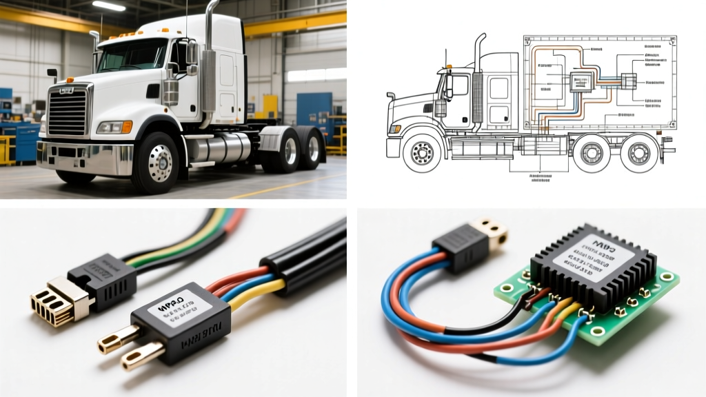
The Critical Role of Accurate Mack Truck Wiring Diagrams
Diagnosing electrical faults in modern heavy-duty commercial vehicles requires far more than a simple test light and a multimeter. For fleet technicians and owner-operators working on Mack trucks—particularly those equipped with the MP7, MP8, or newer MP8HE engines—access to precise, chassis-specific Mack truck wiring diagrams is non-negotiable. A single misidentified wire color or misunderstood CAN bus pinout can lead to catastrophic ECM failure, misdiagnosed datalink faults, or hours of wasted shop time.
Unlike light-duty vehicles, heavy-duty Mack trucks feature highly customizable electrical architectures. A Mack Anthem day cab will have vastly different harness routing, bulkhead connectors, and auxiliary power module (APM) configurations compared to a sleeper-equipped Mack Pinnacle. This guide compares the leading resources for obtaining accurate schematics, breaks down essential MP8 ECM specifications, and provides a selection matrix to help your shop choose the right diagnostic software.
Comparing the Top Diagram Resources for Heavy-Duty Shops
When sourcing wiring schematics, shops generally choose between OEM proprietary software, comprehensive aftermarket subscription services, and fault-code-driven diagnostic suites. Here is how the top contenders stack up.
1. Mack Premium Tech Tool (PTT) & OEM Service Portal
The Mack Premium Tech Tool (PTT) combined with the OEM Service Information portal is the gold standard for dealership-level diagnostics. PTT provides dynamic, interactive wiring diagrams that highlight the exact circuit path from the battery distribution box to the specific component pin.
- Pros: 100% accurate to the specific VIN. Includes bulkhead connector pinouts, splice pack locations, and exact OEM wire color codes (e.g., distinguishing between a white/red tracer and a red/white tracer).
- Cons: High initial cost for the PTT hardware and software licenses. The interface can be notoriously slow and clunky compared to modern web-based platforms.
2. Mitchell 1 TruckSeries
Mitchell 1 TruckSeries is the backbone of many independent heavy-duty repair shops. It aggregates OEM data into a standardized, user-friendly interface.
- Pros: Excellent flat-rate integration, standardized diagram layouts, and robust component location guides. The wiring diagrams are redrawn for consistency, making them easier to read for technicians accustomed to light-duty schematics.
- Cons: Redrawn diagrams occasionally omit proprietary OEM splice points or specific harness tape-wrap notes that are critical for waterproofing repairs.
3. Noregon NextStep Repair
Noregon approaches wiring diagrams from a fault-code-first perspective. When a J1939 datalink code or an MP8 sensor fault is pulled via JPRO, NextStep isolates the exact circuit involved.
- Pros: Eliminates the need to sift through 40-page chassis wiring PDFs. Provides step-by-step pinout testing values (voltage and resistance) specific to the active fault.
- Cons: Not ideal for custom upfitting, PTO installations, or tracing non-emissions-related chassis lighting circuits.
4. Aftermarket PDF Compilations
Many technicians resort to downloading generic PDF bundles from eBay or third-party forums. Our expert verdict: Avoid these for critical ECM or datalink diagnostics. These manuals often lack chassis-specific addendums, leading to severe misdiagnoses when dealing with Mack's Body Builder Module or multiplexed switch networks.
Technical Reference: Mack MP8 ECM & J1939 Datalink Specifications
To illustrate the level of detail required when using Mack truck wiring diagrams, below are the critical baseline specifications for the Mack MP8 engine control module and the SAE J1939 datalink network. For deeper standard definitions, refer to the SAE J1939 Standard documentation.
J1939 CAN Bus Wiring Specifications
The J1939 datalink is the nervous system of the Mack truck. Faults here will cascade across the dash, causing the ABS, transmission TCU, and engine ECM to throw communication SPNs.
| Parameter | CAN High (J1939+) | CAN Low (J1939-) |
|---|---|---|
| Standard Wire Color | Yellow | Green |
| Wire Gauge (AWG) | 18 AWG or 20 AWG | 18 AWG or 20 AWG |
| 9-Pin Diag. Connector | Pin 3 | Pin 1 |
| Voltage (Key ON) | 2.5V to 3.5V | 1.5V to 2.5V |
| Terminating Resistor | 120 Ohms at each end of the backbone (60 Ohms total in parallel) | |
Mack MP8 ECM Power, Ground, and Actuator Pinouts
When testing the MP8 ECM, verifying clean power and ground is the first step before condemning the module. The following specifications apply to the primary ECM connectors (typically a 120-pin or multi-cavity Deutsch/AMP setup depending on the exact emissions year).
| Circuit Function | Wire Color (Typical) | AWG Size | ECM Pin / Connector |
|---|---|---|---|
| Main Battery Positive | Red | 10 AWG | ECM Pin A1 / A2 |
| Main Battery Ground | Black | 10 AWG | ECM Pin A3 / A4 |
| Key-On Ignition Power | White w/ Red Tracer | 14 AWG | ECM Pin A15 |
| VGT Actuator Power | Red w/ White Tracer | 14 AWG | VGT 2-Pin Deutsch |
| Engine Brake Solenoid 1 | Brown w/ Yellow | 18 AWG | ECM Low-Side Driver |
Note: Always verify against the specific VIN diagram via the Mack Trucks Service Support portal, as wire colors can vary between EPA07, EPA10, and GHG17 emissions packages.
Selection Matrix: Matching Software to Shop Volume
Choosing the right resource for Mack truck wiring diagrams depends on your shop's operational model. Use the matrix below to guide your purchasing decision.
| Resource Type | Best Suited For | Cost Profile | Diagram Accuracy |
|---|---|---|---|
| OEM PTT Portal | Mack Dealerships, Warranty Repair Centers | High (Hardware + Annual Sub) | 100% VIN-Specific |
| Mitchell 1 TruckSeries | Independent Heavy-Duty Shops, Fleet Maintenance | Medium (Monthly Subscription) | 95% (Standardized) |
| Noregon NextStep | Diagnostics-First Shops, Mobile Techs | Medium (Per-Code or Sub) | High (Circuit Specific) |
| Generic PDF Bundles | Owner-Operators, Basic Lighting Repairs | Low (One-time purchase) | Variable / Unreliable |
Real-World Troubleshooting: Tracing a J1939 Datalink Fault
Even with the best Mack truck wiring diagrams in hand, technicians must know how to physically validate the schematic. A common scenario is a Mack Anthem presenting a dash full of warning lights and an active SPN 192 (J1939 Network Data Received but in Error).
Step-by-Step Diagnostic Tree
- Verify the 60-Ohm Rule: Turn the ignition OFF. Connect a multimeter set to Ohms across Pin 3 (CAN High) and Pin 1 (CAN Low) on the 9-pin diagnostic connector in the cab. You must read exactly 60 ohms. This confirms both 120-ohm terminating resistors (one in the ECM, one at the end of the backbone) are intact and in parallel.
- Analyze Deviations:
- Reading 120 Ohms: One terminating resistor is open or missing. Consult your wiring diagram to locate the physical resistor pucks (often near the ECM or the instrument cluster bulkhead).
- Reading 0 to 5 Ohms: CAN High and CAN Low are shorted together. Look for chafed harnesses where the yellow and green wires rub against the firewall or battery box.
- Check for Voltage Bias: Turn the ignition ON (engine OFF). Measure DC voltage from Pin 1 (CAN Low) to Battery Ground (should be ~1.5V to 2.5V). Measure Pin 3 (CAN High) to Battery Ground (should be ~2.5V to 3.5V). If CAN High reads 0V, the ECM is likely not powering up the datalink transceiver, indicating a blown ECM internal fuse or a failed APM relay.
- Validate Shielding: Inspect the bare drain wire integrated into the J1939 twisted pair. If the shield is grounded at multiple points along the chassis, it can create a ground loop, inducing electromagnetic interference (EMI) from the alternator into the data lines.
Best Practices for Heavy-Duty Electrical Repairs
When executing repairs based on Mack truck wiring diagrams, adhere strictly to heavy-duty electrical standards. Never use solder on engine harnesses; the vibration of a diesel engine will cause soldered joints to work-harden and snap. Instead, use OEM-spec crimp connectors with adhesive-lined, dual-wall heat shrink tubing. For high-current circuits like the 4/0 AWG starter cables or the 2/0 AWG alternator feeds, always use a hydraulic crimp tool and apply dielectric grease to the terminal lugs to prevent galvanic corrosion. By combining the right diagram software with rigorous physical testing protocols, you can eliminate electrical ghosts and return Mack trucks to the road faster.