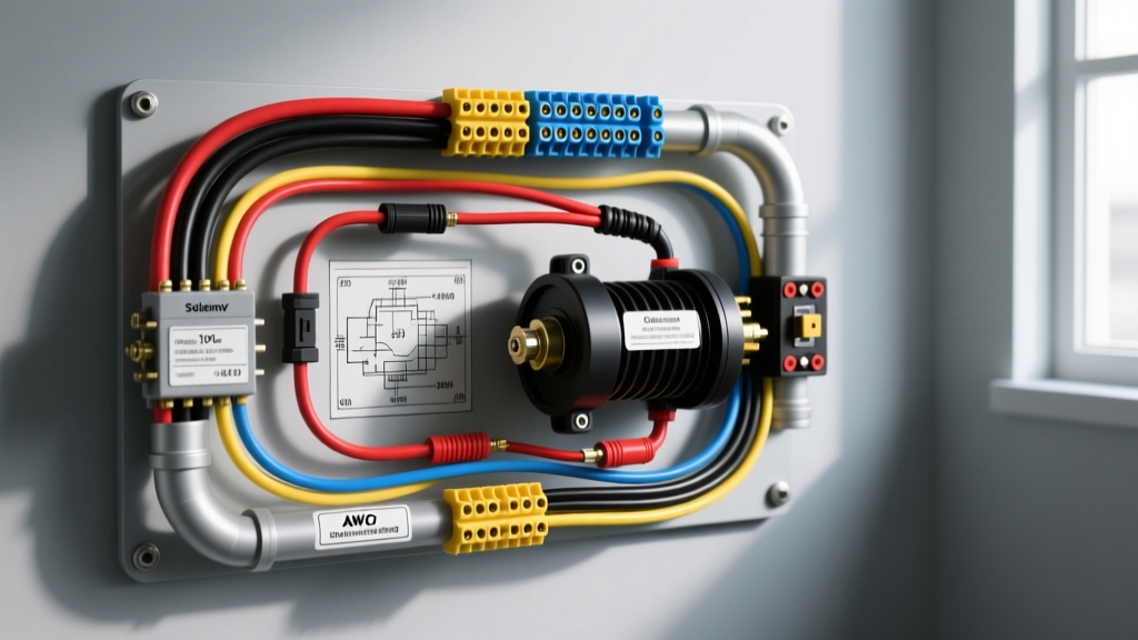
Understanding the Electrical Demands of a 12V Winch
Deploying a 12V electric winch for vehicle recovery introduces massive transient electrical loads to your automotive charging system. A standard 12,000 lb rated winch can draw upwards of 400 to 450 amps under peak stall conditions. Standard OEM vehicle wiring, alternator outputs, and factory battery terminals are entirely inadequate for this amperage. A properly executed wiring diagram for 12V winch systems must prioritize heavy-gauge cabling, high-amperage circuit protection, and robust solenoid switching to prevent voltage drop, thermal runaway, and catastrophic electrical fires.
This complete wiring walkthrough details the exact architecture required for safe, high-performance winch integration on trucks, Jeeps, and SUVs. We will cover solenoid contactor pinouts, AWG cable sizing, control circuit routing, and critical torque specifications.
The Core Wiring Diagram for 12V Winch Systems
The fundamental architecture of a 12V winch electrical system relies on a heavy-duty 4-post continuous duty solenoid (contactor) to isolate the massive motor current from the low-amperage control switches. Directly switching 400 amps via a handheld pendant or dashboard switch would instantly melt the control wiring and pose a severe safety hazard.
Solenoid Contactor Pack Pinout & Routing
Most premium winch systems utilize an Albright-style DC88-4 or Trombetta 4-post continuous duty contactor. The pin configuration and wire routing are as follows:
- Post 1 (Motor A): Connects to the winch motor terminal A. Typically utilizes a Yellow or Orange 2 AWG cable.
- Post 2 (Motor B): Connects to the winch motor terminal B. Typically utilizes a Green or Blue 2 AWG cable.
- Post 3 (Battery Positive): Connects to the vehicle battery positive terminal via a main circuit breaker. Utilizes a Red 2 AWG or 1/0 AWG cable.
- Post 4 (Ground): Connects to the vehicle chassis ground or directly to the battery negative terminal. Utilizes a Black 2 AWG or 1/0 AWG cable.
- Small Terminal 1 (Coil +): Receives switched 12V+ from the control relay or wireless receiver. (12 AWG Red wire).
- Small Terminal 2 (Coil -): Connects to chassis ground to complete the solenoid coil circuit. (12 AWG Black wire).
When the control circuit applies 12V to the coil terminals, the internal electromagnet pulls the heavy copper contact disc down, bridging Post 3 and Post 4 to the motor posts, thereby energizing the winch motor in the desired direction.
Cable Sizing: AWG Specifications and Voltage Drop
Undersized winch cables lead to severe voltage drop, which exponentially decreases the winch's pulling power and line speed while generating dangerous heat within the cable insulation. According to the SAE J1128 Low Tension Primary Cable Standard and marine electrical best practices, winch power cables must be sized based on the maximum expected amperage and the total round-trip cable length (from battery to winch and back to ground).
Always use pure stranded copper wire with fine stranding (SAE J1128 Type SXL or GXL) to withstand high-vibration environments and engine bay heat. Avoid Copper Clad Aluminum (CCA) wire, which has higher resistance and is prone to galvanic corrosion at crimp terminals.
| Winch Rated Pull (lbs) | Max Amp Draw (Stall) | Minimum AWG Size | Recommended Circuit Breaker |
|---|---|---|---|
| 3,000 - 4,500 | 150A - 200A | 4 AWG | 150A - 200A DC |
| 8,000 - 10,000 | 300A - 350A | 2 AWG | 250A Class T Fuse |
| 12,000 - 14,000 | 400A - 450A | 1/0 AWG | 400A ANL / Class T |
| 16,000+ | 500A+ | 2/0 AWG | 500A Class T Fuse |
Step-by-Step Wiring Walkthrough
1. Battery and Ground Preparation
Begin by disconnecting the vehicle's negative battery terminal. Install a heavy-duty marine-grade circuit breaker or Class T fuse within 7 inches of the battery positive post. This proximity is critical; an unprotected cable shorting against the chassis will weld itself to the metal and start a fire in seconds. Terminate your main 1/0 AWG or 2 AWG positive cable with a 3/8-inch tinned copper ring terminal. Use adhesive-lined marine heat shrink over the crimp barrel to prevent moisture ingress and corrosion. Torque the battery terminal hardware to 10-12 ft-lbs.
2. Solenoid Pack Integration
Mount the solenoid contactor pack in a protected, dry area of the engine bay or inside a dedicated control box. Route the main positive cable from the circuit breaker to Post 3 on the solenoid. Route the main ground cable from the battery negative (or a verified clean chassis ground point) to Post 4. Ensure all hardware on the large solenoid posts is tightened to 12-15 ft-lbs to prevent micro-arcing and terminal overheating.
3. Motor Lead Routing and Quick-Connects
Route the Motor A and Motor B cables to the winch housing. Keep these cables away from exhaust headers, steering shafts, and sharp suspension components. Protect the cables with split loom tubing and secure them every 12 inches with UV-resistant zip ties. If you are running a multi-mount setup (front and rear receiver hitches), integrate an Anderson Powerpole SB350 quick-disconnect plug. The SB350 is rated for 350 amps continuous and utilizes a polycarbonate housing that resists impact and water intrusion. Crimp the SB350 contacts using a dedicated hydraulic or heavy ratchet crimper to ensure a gas-tight connection.
Control Circuit Integration and In-Cab Switches
The control circuit dictates how the solenoid is triggered. While many winches come with a basic wired pendant, integrating an in-cab switch or wireless receiver requires a secondary automotive relay to protect the vehicle's wiring harness.
- Power Source: Tap into an ignition-switched 12V+ source in the fuse box using an Add-A-Circuit fuse tap. This ensures the winch cannot be accidentally deployed when the vehicle is off, and prevents parasitic battery drain from the solenoid coil.
- Relay Integration: Wire a standard 40A SPST automotive relay. Pin 30 receives the switched 12V+. Pin 87 feeds the small Coil + terminal on the winch solenoid. Pin 85 is triggered by your dashboard momentary switch, and Pin 86 goes to ground.
- Wire Gauge: Use 12 AWG primary wire for all control circuit routing. Secure the wiring with T-taps or solder-seal connectors rather than cheap scotch locks, which vibrate loose off-road.
Common Failure Modes and Troubleshooting
Even with a flawless wiring diagram for 12V winch setups, extreme environments lead to specific electrical failure modes. Use a digital multimeter (DMM) to diagnose these common issues:
- Solenoid Sticking (Welded Contacts): If the winch continues to run after releasing the switch, the high amperage has likely caused micro-arcing inside the solenoid, welding the copper contact disc to the posts. Fix: Immediately disconnect the main battery cable. Replace the contactor pack; never attempt to clean or file the internal contacts.
- Severe Voltage Drop Under Load: If the winch bogs down and headlights dim excessively, measure the voltage drop across the positive cable and the ground cable while the winch is under load. A reading greater than 0.5V across any single cable indicates high resistance. Fix: Check for loose terminal crimps, corroded ring terminals, or undersized AWG wiring. Refer to the Blue Sea Systems Wire Sizing Guide for recalculation.
- Control Circuit Failure: If the solenoid clicks but the motor does not turn, or there is no click at all, test the small coil terminals for 12V+ during switch actuation. If voltage is present but the solenoid doesn't pull in, the internal coil is burned out. If no voltage is present, trace the 12 AWG control wiring back to the ignition relay and dashboard switch.
Authoritative References
For further technical specifications, OEM torque values, and advanced dual-battery isolation diagrams, consult the following resources:
- Warn Industries Installation Manuals - Comprehensive guides for OEM and aftermarket winch control box wiring.
- SAE J1128 Standard - Specifications for low tension primary automotive cable insulation and temperature ratings.
- Blue Sea Systems Circuit Protection - Marine and off-road DC voltage drop calculations and ABYC compliance standards.