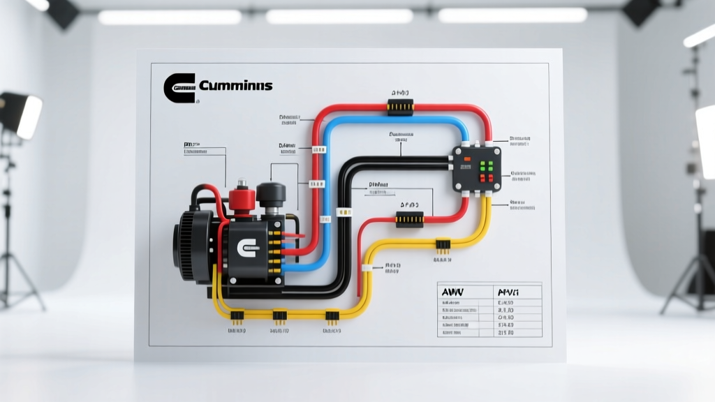
Technical Reference: Navigating the Cummins Generator Wiring Diagram PDF
Integrating a Cummins-powered mobile generator set—whether for luxury RV applications, mobile command centers, or industrial off-grid vehicular setups—requires a precise understanding of the electrical architecture. The official Cummins generator wiring diagram PDF serves as the master blueprint for these complex systems, detailing everything from the primary DC cranking circuits to the high-voltage AC output and CAN bus communication networks. As an automotive electrical specialist, relying on memory or generic diagrams is a recipe for catastrophic ECU failure or electrical fires. This technical specification reference breaks down the critical wire gauges, OEM color codes, terminal pinouts, and torque specifications required to properly wire, diagnose, and maintain Cummins mobile generator platforms, including the popular PowerCommand control systems and Onan QuietDiesel series.
Understanding Schematic Standards and Wire Insulation
Before tracing circuits within the Cummins generator wiring diagram PDF, technicians must understand the insulation standards governing the harness. Mobile generator sets operate in high-vibration, high-ambient-temperature environments. Therefore, Cummins mandates the use of SAE J1128 compliant wiring, specifically TXL (Thin-wall Cross-linked Polyethylene) or GXL (General-purpose Cross-linked Polyethylene) for engine bay routing. These insulation types withstand continuous temperatures up to 125°C (257°F) and resist degradation from diesel fuel and oil exposure.
When reading the PDF schematics, note that Cummins utilizes a grid-reference system (e.g., A1-F10) to locate specific relays, fuses, and ground distribution blocks. Ground points are typically designated with a "G" followed by a three-digit number (e.g., G104), which corresponds to the physical chassis or engine block grounding stud.
Primary DC Power and Control Harness Specifications
The DC control harness is the lifeline of the generator set, providing cranking amperage, ECU logic power, and pre-heating currents. Undersizing these wires or using improper terminal crimps leads to voltage drop, resulting in "Low Battery Voltage" shutdown codes (e.g., Fault Code 32 or 36) during the crank cycle. Below is the standard specification chart for the primary DC input and remote control interface.
| Circuit Function | Wire Color (OEM) | AWG Size | Connector / Terminal Type | Max Voltage Drop Allowance |
|---|---|---|---|---|
| B+ (Battery Positive Supply) | Red | 2/0 AWG | M10 Ring Terminal (Crimped/Soldered) | < 0.2V @ 200A Crank |
| B- (Battery Negative / Ground) | Black | 2/0 AWG | M10 Ring Terminal to Chassis Busbar | < 0.2V @ 200A Crank |
| Ignition / Run Signal (Remote) | Yellow | 14 AWG (TXL) | Deutsch DT / Ampseal Cavity 4 | < 0.5V |
| Pre-Heat / Glow Plug Relay Trigger | Blue | 10 AWG (TXL) | Spade Connector / 30A Relay Coil | < 0.3V |
| ECU Constant Memory (Keep-Alive) | Red w/ White Trace | 16 AWG (TXL) | Fused (5A) inline to Ampseal | N/A (Logic Level) |
| AC Sense / Voltage Reference | White | 18 AWG (TXL) | Sealed Bullet Connector | N/A (High Impedance) |
PowerCommand ECU Pinout Configuration
Modern Cummins mobile generators utilize the PowerCommand Control (PCC) module or equivalent Bosch-derived ECU architectures. The main ECU connector is typically a 60-pin or 80-pin Ampseal or Molex MX150 sealed connector. Proper pin seating and moisture sealing are critical; a single backed-out pin in the CAN bus circuit will cause the generator to lose communication with the remote RV dashboard display.
Core ECU Interface Pinout (Reference Block A & B)
| Pin Number | Signal Designation | Wire Color | AWG | Technical Description & Diagnostic Notes |
|---|---|---|---|---|
| A1 | B+ Sense | Red | 14 | Monitors main battery voltage. If < 10.5V, ECU inhibits crank. |
| A2 | Logic Ground | Black | 14 | Dedicated ECU ground. Must not share a stud with high-current loads. |
| B12 | CAN High (J1939) | Yellow | 18 | SAE J1939 Data Link High. Requires 120-ohm terminating resistor. |
| B13 | CAN Low (J1939) | Green | 18 | SAE J1939 Data Link Low. Check for 60-ohm parallel resistance across B12/B13. |
| C4 | Magnetic Pickup (MPU) + | Shielded Pair | 20 | Reads flywheel ring gear teeth for RPM calculation. Shield grounded at ECU only. |
| C5 | Magnetic Pickup (MPU) - | Shielded Pair | 20 | Air gap must be set to 0.020" - 0.030" for clean sine wave signal. |
Alternator Output and AC Transfer Switch Integration
The AC output side of the Cummins generator wiring diagram PDF details the routing from the alternator stator windings to the main circuit breaker, and subsequently to the vehicular Automatic Transfer Switch (ATS) or direct RV distribution panel. For a standard 8kW to 12kW mobile diesel generator, the output is typically 120/240V Single Phase, 60Hz.
- L1 and L2 (Hot Legs): Sized at 4 AWG to 2 AWG THHN/MTW depending on the breaker rating (30A vs 50A). These must be routed in separate conduit from the DC control harness to prevent electromagnetic interference (EMI) from disrupting the ECU logic.
- Neutral (N): Bonded to the generator frame ground only at the generator stator housing (per NEC and RVIA standards). The neutral wire must be identical in gauge to the hot legs.
- Protective Earth (PE): A dedicated 6 AWG green/yellow ground wire connects the alternator housing to the vehicle chassis ground busbar. This ensures fault current has a low-impedance path to trip the main AC breaker in the event of a stator short.
Sensor Sub-Harnesses and Actuator Wiring
The engine sensor sub-harness routes through high-heat zones near the exhaust manifold and turbocharger. According to Cummins Power Generation Installation Guidelines, all sensor wiring in these zones must be wrapped in fiberglass or high-temperature silicone sleeving.
Oil Pressure Sender: Typically a 3-wire active sensor (5V Reference, Signal Return, Sensor Ground). Using a standard 1-wire automotive idiot-light sender on a Cummins ECU will result in an immediate "Sensor Open/Short" fault and engine derate.
Coolant Temperature Sensor: A 2-wire NTC thermistor. Resistance drops as temperature rises. At 20°C (68°F), resistance should read approximately 2,500 ohms; at 80°C (176°F), it should drop to roughly 300 ohms. Wire colors are typically Gray (Signal) and Black/Yellow (Ground).
Torque Specifications and Connector Best Practices
Electrical failures in mobile generators are rarely caused by the wire itself, but rather by poor terminations and vibration-induced loosening. When executing the wiring outlined in the PDF schematic, adhere strictly to the following mechanical specifications:
- M8 Alternator/Starter Terminal Studs: 18 - 22 Nm (13 - 16 lb-ft). Use a flat washer and a split lock washer or Nord-Lock washer to prevent vibration backing.
- 2/0 AWG Copper Lugs on DC Busbar: 35 - 40 Nm (26 - 30 lb-ft). Ensure the lug barrel is crimped with a calibrated hex-die crimper, and apply dielectric grease to the stud before final torque to prevent galvanic corrosion.
- Deutsch DT Connectors: Always use the secondary wedge lock (yellow or red plastic insert) after seating the pins. Push the wire in until you hear a tactile "click," then pull back with 2-3 lbs of force to verify retention before inserting the wedge.
Troubleshooting Common Harness Faults via Schematic
When a mobile Cummins generator throws an active fault code, the wiring diagram PDF is your primary diagnostic tool. For example, if the unit displays a Code 19 (Governor Actuator Fault), the schematic will direct you to the actuator harness. Instead of immediately replacing the $400 actuator, perform a voltage drop test on the PWM (Pulse Width Modulated) supply and ground wires while the ECU is attempting to prime the fuel rail. If the voltage drop across the ground wire exceeds 0.1V, the fault is a degraded ground splice, not a failed actuator. Similarly, if the remote start panel fails to communicate, reference the CAN bus pins (B12/B13). Disconnect the battery, isolate the ECU, and measure resistance across the CAN High and Low pins at the remote display connector. A reading of 120 ohms indicates a missing terminating resistor; a reading of 0 ohms indicates a dead short in the harness; a reading of 60 ohms confirms the physical data link is intact, pointing to a software or module-level failure.
Authoritative References and Manual Sourcing
For exact model-year variations, always cross-reference this guide with the specific serial number of your generator set. You can download the exact Cummins generator wiring diagram PDF for your unit by accessing the Cummins Official Support Portal and entering your generator's serial number (ESN). Ensure you are referencing the "Installation Manual" (I-manual) and the "Service Manual" (S-manual), as the wiring schematics are typically located in Section 9 or 10 of these comprehensive documents. Never rely on third-party forum scans, as pinouts change significantly between Tier 3 and Tier 4 emissions-compliant ECU generations.