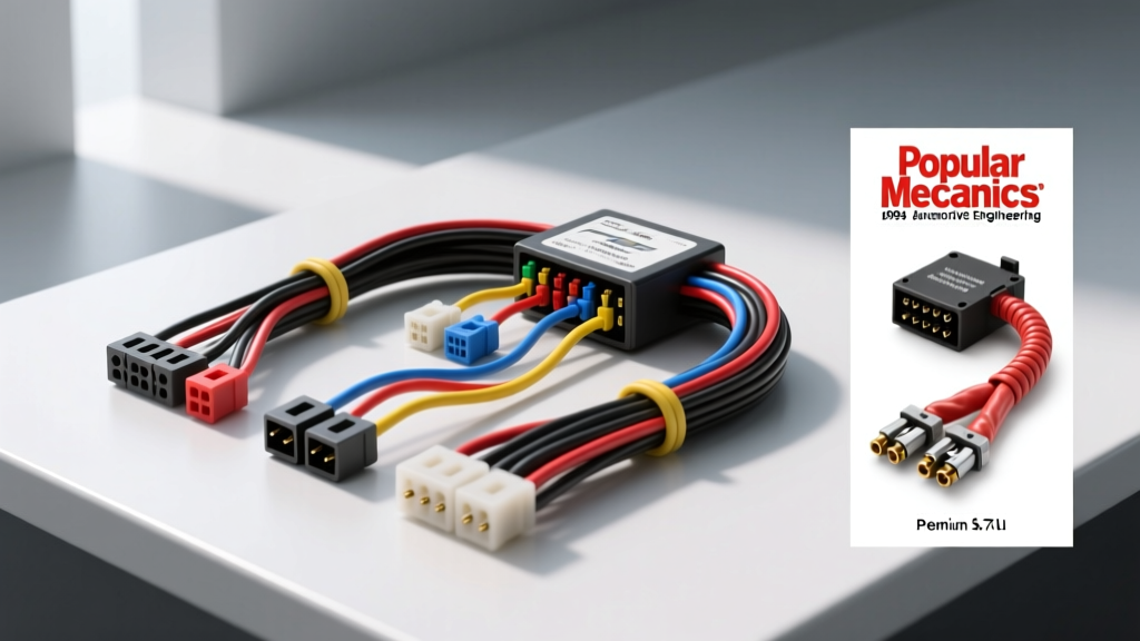
Decoding the 1994 Chevy 5.7 TBI Wiring Harness Diagram
Restoring a classic C/K truck or executing an engine swap with a legendary 350 cubic-inch V8 requires a flawless electrical foundation. The 1994 Chevy 5.7L Throttle Body Injection (TBI) system represents the pinnacle of GM's OBD-I speed-density fuel management. However, after three decades of underhood heat cycles, oil exposure, and vibration, the original wiring harness becomes brittle, leading to erratic idle stumbles, rich-running conditions, and mysterious Check Engine lights. When sourcing a replacement, the 1994 Chevy 5.7 TBI wiring harness diagram is not just a troubleshooting map—it is your ultimate product selection baseline. By understanding the OEM schematic, you can critically evaluate whether an aftermarket universal harness or a direct-fit OEM reproduction will meet your specific build requirements.
Why the OEM Schematic is Your Ultimate Buying Metric
Many universal aftermarket harnesses 'simplify' the factory wiring diagram to appeal to novice installers. While this makes initial routing easier, it often omits critical electromagnetic interference (EMI) shielding, dedicated sensor grounds, and specific splice nodes (identified as 'S' nodes on GM blueprints). For instance, the Electronic Spark Control (ESC) knock sensor circuit requires a dedicated shielded wire to prevent the ECM from falsely pulling ignition timing. If a replacement harness substitutes this with standard unshielded primary wire, your 5.7L will suffer from severe spark knock under load. Cross-referencing product spec sheets against the factory GM schematic ensures you do not sacrifice drivability for ease of installation.
Harness Selection Matrix: OEM vs. Aftermarket vs. Custom
When replacing the engine and ECM portion of the harness, buyers generally choose between three distinct product categories. Below is a comparison guide to help you select the right harness based on your project scope.
| Feature | OEM Reproduction (e.g., M&H Electric) | Universal TBI Kit (e.g., Painless 60101) | Custom Mil-Spec (e.g., Rywire/EWAYS) |
|---|---|---|---|
| Wire Type | PVC / Standard Primary (GXL) | Cross-Linked (TXL) High-Temp | Tefzel (M22759) Mil-Spec |
| ECM Compatibility | Exact Match (1228746 / 16197427) | Requires minor pin swapping | Built to exact ECM spec |
| Connectors | OE Weather-Pack & Metri-Pack | Standard Weather-Pack | Sealed Autosport / Deutsch |
| Loom Material | Split Loom / OEM Tape | Split Loom | Raychem DR-25 / Braided |
| Best Application | Concours Restorations & Stock Rebuilds | Engine Swaps & Off-Road Trucks | High-Performance & Show Builds |
Critical Wire Codes and AWG Specifications
A high-quality replacement harness must adhere to SAE J1128 specifications for low-tension primary cable. The 1994 TBI diagram dictates specific American Wire Gauge (AWG) sizes to handle current loads without voltage drop. Injector driver circuits, for example, require thicker wires to handle the peak-and-hold current spikes of the low-impedance TBI injectors.
| Circuit / Sensor | OE Wire Color | Required AWG | Function & Notes |
|---|---|---|---|
| Injector 1 (Driver) | Tan/White | 18 AWG | Peak-and-hold driver for Bank 1 |
| Injector 2 (Driver) | Tan/Black | 18 AWG | Peak-and-hold driver for Bank 2 |
| MAP Sensor Signal | Light Green | 20 AWG | Analog voltage return to ECM |
| TPS Signal | Dark Blue | 20 AWG | Throttle blade position feedback |
| Coolant Temp (CTS) | Yellow | 20 AWG | Thermistor signal for fuel enrichment |
| Knock Sensor (ESC) | White (Shielded) | 22 AWG | Must retain shield drain wire to prevent EMI |
| ECM Battery Feed | Orange | 14 AWG | Constant 12V for Keep-Alive Memory (KAM) |
ECM Pinout Verification and Grounding Strategy
The 1994 5.7L TBI typically utilizes the GM ECM 1228746 (or the flash-tunable 16197427). When auditing a replacement harness, verify that the main ECM bulkhead connector matches the OEM pinout. A common flaw in cheap imported harnesses is the misalignment of the 5-volt reference pins, which will instantly fry your MAP and TPS sensors upon key-on.
Furthermore, the GM wiring diagram highlights specific ground nodes that must be respected. The TBI ECM relies on dedicated, clean grounds rather than sharing chassis grounds with high-draw accessories. According to the factory schematic, G103 is located on the right cylinder head, and G104 is mounted on the thermostat housing. If your aftermarket harness combines these sensor grounds with the high-amperage starter ground, the voltage differential will cause the ECM to read false coolant temperatures, resulting in a perpetually rich idle and fouled spark plugs.
Common Failure Modes in Aging '94 TBI Harnesses
If you are attempting to salvage your original harness instead of buying a replacement, use the wiring diagram to locate these notorious failure points:
- ALDL Connector Corrosion: The 12-pin Assembly Line Diagnostic Link under the dash is prone to pin oxidation. The dark green wire (Pin E) and black ground (Pin A) often lose continuity, preventing scanner communication.
- Firewall Bulkhead Chafing: The main harness passes through a rubber grommet near the brake booster. Over time, the grommet degrades, allowing the harness to rub against the firewall sheet metal, shorting the 14 AWG ignition feed to ground.
- Oil Pressure Sender Wire Degradation: The single-wire sender (usually dark green or brown) routes dangerously close to the exhaust manifold and oil filter. It frequently becomes brittle, cracks, and grounds out against the engine block, causing the dash gauge to read zero and potentially disabling the fuel pump relay safety circuit.
- Injector Connector Latch Failure: The plastic locking tabs on the TBI injector Weather-Pack connectors become brittle and snap off, allowing the connectors to vibrate loose during heavy throttle application.
Installation and Routing Best Practices
When installing your selected harness, reference the Painless Performance TBI Installation Manual or the GM factory service guide for proper drip-loop creation. Always route sensor wires (like the O2 sensor and CTS) away from high-voltage ignition components such as the distributor cap and HEI coil wire. Use adhesive-lined heat shrink on any necessary splices to prevent moisture ingress, and secure the harness using nylon P-clips rather than zip-ties directly against sharp bracket edges. By treating the wiring diagram as a strict engineering blueprint rather than a mere suggestion, your 1994 Chevy 5.7L TBI will deliver reliable, factory-intended performance for decades to come.
References: GM 1994 C/K Truck Service Manual (Wiring Diagrams Section); GM Truck Club TBI Pinout Archives; SAE J1128 Low Tension Primary Cable Standard.