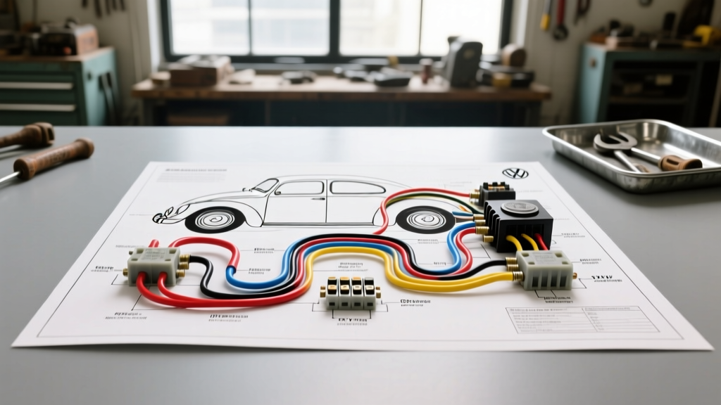
Introduction to the 1970 Air-Cooled Electrical System
For classic car enthusiasts and beginner mechanics, the 1970 Volkswagen Beetle represents a golden era of automotive simplicity. Unlike modern vehicles burdened with complex CAN bus networks and dozens of electronic control modules, the 1970 Beetle relies on a straightforward, analog 12-volt electrical system. By 1970, Volkswagen had fully transitioned away from the earlier 6-volt systems, meaning your Beetle is equipped with a 12-volt Bosch generator, a mechanical voltage regulator, and a basic ceramic fuse box.
Reading a 1970 VW Beetle wiring diagram can initially seem like deciphering a foreign language, primarily because Volkswagen utilized the German DIN (Deutsches Institut für Normung) standard for wire colors and terminal designations. However, once you understand the fundamental logic behind the DIN color codes and the routing of the primary circuits, troubleshooting and repairing the electrical system becomes an incredibly rewarding and manageable task. This guide breaks down the core fundamentals of the 1970 Beetle wiring schematic, providing actionable insights for beginners.
Decoding the Diagram: DIN 72552 Color Codes and Terminals
The most critical step in mastering the 1970 VW Beetle wiring diagram is understanding the DIN 72552 standard. Unlike American vehicles of the same era, which often used arbitrary or inconsistent wire colors, VW strictly adhered to a color-coded system that directly correlated to specific terminal numbers on switches and relays. According to the SAE International DIN 72552 Standard, these colors dictate the function of the wire regardless of where it is routed in the vehicle.
| Wire Color | DIN Terminal | Circuit Function | Typical AWG Size |
|---|---|---|---|
| Red | 30 | Constant Battery Positive (+12V direct from battery) | 10 AWG - 4 AWG |
| Black | 15 | Switched Ignition Power (+12V only when key is ON) | 14 AWG - 12 AWG |
| Brown | 31 | Ground / Earth (Returns to battery negative or chassis) | 14 AWG - 10 AWG |
| White | 56a | Headlight High Beam | 14 AWG |
| Yellow | 56b | Headlight Low Beam | 14 AWG |
| Green | 58 | Parking Lights / Tail Lights / Dash Illumination | 16 AWG - 14 AWG |
| Blue | 58b | License Plate Light / Instrument Cluster Dimmer | 16 AWG |
| Green/Black | 61 / D+ | Generator Excitation / Charge Indicator Light | 14 AWG |
When tracing a fault on your wiring diagram, always look at the terminal number on the switch or component. If you are testing terminal 15 on your ignition switch, you should expect to see 12 volts on a black wire only when the key is in the 'Run' position. If you measure 0 volts, you know the fault lies between the battery (Terminal 30) and the ignition switch input.
Core Circuits Explained for Beginners
1. The 12V Generator and Voltage Regulator Circuit
The 1970 Beetle utilizes a Bosch 35-amp external-generator setup. Unlike modern alternators that have internal regulators, the Beetle's generator relies on a mechanical voltage regulator mounted on the left side of the engine bay firewall. The wiring diagram for this circuit revolves around three primary terminals on the generator: B+, D+, and DF.
- B+ (Battery Positive): This is the main charging output. It is connected via a heavy 10 AWG red wire directly to the positive terminal of the battery (often routed through the starter solenoid post). If this wire is corroded or undersized, your battery will not receive adequate charging current.
- D+ (Dynamo/Excitation): This terminal is connected to the red 'GEN' warning light on your dashboard via a 14 AWG blue/black wire. When you turn the key to the 'ON' position, battery voltage flows through the bulb to the D+ terminal, providing the initial magnetic excitation the generator needs to start producing power. Once the generator spins fast enough, it produces its own voltage, equalizing the potential on both sides of the bulb, causing the light to turn off.
- DF (Dynamo Field): This wire runs directly to the mechanical voltage regulator to control the strength of the generator's electromagnetic field, regulating the final output voltage to roughly 13.8V - 14.2V.
2. Headlight and Parking Light Routing
The front lighting circuit on a 1970 Beetle is notoriously simple but prone to specific failure modes. Power leaves the headlight switch (E1) and travels to the dimmer relay or floor-mounted dimmer switch (depending on exact build date and market). From there, the current splits into White (56a) for high beams and Yellow (56b) for low beams.
A critical beginner mistake is assuming the headlight buckets are properly grounded through the sheet metal. While the factory wiring diagram shows the ground completing through the chassis, decades of rust, paint, and vibration often break this ground path. Expert Tip: Always install a dedicated 14 AWG brown ground pigtail from the headlight bulb ground prong directly to a clean, bare-metal bolt on the inner fender. This single modification solves 90% of dim headlight complaints on air-cooled VWs.
3. Fuse Box and Switched Ignition Power
The 1970 Beetle features a 10-slot fuse box located under the dashboard on the driver's side. It uses European-style ceramic 'torpedo' fuses. It is vital for beginners to understand that European ceramic fuses are rated differently than modern American SAE blade fuses. A standard VW 8-amp (white) fuse is designed to blow at 8 amps continuous, whereas an American 10-amp blade fuse might hold 12 amps before blowing. Never replace an 8A ceramic fuse with a higher-rated piece of foil or wire, as the 14 AWG wiring harness will melt before the fuse blows in a dead-short scenario.
Common Grounding Issues and Troubleshooting
The most pervasive issue found when studying the 1970 VW Beetle wiring diagram in real-world applications is inadequate grounding. The Beetle's body is mounted on a separate floor pan via rubber body mounts. Because rubber is an insulator, the factory installed heavy braided ground straps to connect the engine, transmission, chassis, and body.
If your starter clicks but won't turn, or your tail lights flicker when you hit the brakes, you are likely suffering from a ground deficiency. Use a digital multimeter to perform a voltage drop test. Set your meter to DC Volts, place the red probe on the battery negative post, and the black probe on the engine block while cranking the starter. A reading higher than 0.10V indicates a poor ground connection. Clean the battery-to-chassis and transmission-to-chassis ground straps with a wire brush and apply dielectric grease to prevent future corrosion.
Troubleshooting Decision Tree: Generator Light Stays On
A common scenario for beginners is the red GEN light remaining illuminated while driving. Follow this diagnostic tree:
- Check Belt Tension: A loose alternator/generator belt will cause slipping, preventing the rotor from reaching excitation speed. Deflection should be roughly 1/2 inch under moderate thumb pressure.
- Test the D+ Wire: Disconnect the blue/black wire from the D+ terminal on the generator. With the ignition ON, the GEN light should go out. If it stays on, you have a short to ground in the wiring harness between the dash and the engine bay.
- Inspect the Voltage Regulator Ground: The mechanical voltage regulator must be grounded to the chassis to function. If the mounting screws are rusted or painted over, the regulator cannot sense system voltage, causing the generator to overcharge or undercharge, keeping the GEN light illuminated.
- Test Generator Output: Use a multimeter at the battery. At 2,000 RPM, you should read between 13.8V and 14.2V. If you read 12.6V or less, the generator brushes may be worn out, or the internal armature is faulty.
Authoritative Resources for Air-Cooled VWs
While understanding the fundamentals is crucial, having the correct reference material on your workbench is non-negotiable. For the most accurate, factory-correct schematics and torque specifications, we highly recommend consulting the Bentley Publishers Volkswagen Service Manuals. Their reproductions of the factory wiring diagrams are color-coded and include vital connector pinout charts that generic manuals often omit.
Additionally, for community-driven troubleshooting and modern wiring harness upgrades (such as converting to modern H4 headlights or replacing the generator with a modern 1-wire alternator), the technical archives at Aircooled.net Wiring Resources provide invaluable, real-world testing data and AWG upgrade charts tailored specifically for the air-cooled platform.
By respecting the DIN color codes, ensuring robust chassis grounds, and utilizing the proper ceramic fuse ratings, you can confidently diagnose, repair, and upgrade the electrical system of your 1970 VW Beetle. The air-cooled wiring diagram is not a maze; it is a logical, elegant map that rewards those who take the time to learn its language.