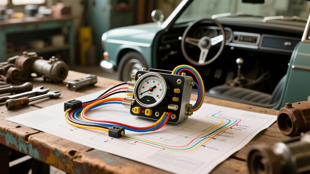
Introduction to Automotive Ammeters
For classic car restorers and custom builders, the dashboard gauge cluster is the nerve center of the vehicle. Among these gauges, the ammeter (or ampere meter) is often the most misunderstood. While modern vehicles rely on voltmeters and computerized battery current sensors, classic muscle cars and trucks from the 1960s and 1970s utilized analog ammeters to monitor the health of the charging system. When studying a factory service manual, the wiring diagram ampere meter section often intimidates beginners because, unlike a simple voltmeter that only requires a switched 12V reference and a ground, an ammeter must handle the entire electrical load of the vehicle.
This guide breaks down the fundamentals of reading and executing a wiring diagram ampere meter setup, focusing on classic full-flow loop systems found in popular platforms like the 1969-1972 GM F-Body (Camaro/Firebird) and A-Body (Chevelle/Cutlass). We will cover wire color codes, AWG sizing, safety protocols, and the common pitfalls that lead to melted harnesses or inaccurate readings.
Decoding the Wiring Diagram Ampere Meter
An ammeter measures the flow of electrical current (in Amperes) into and out of the battery. When the engine is running and the alternator is producing more current than the vehicle is consuming, the excess current flows into the battery, and the needle deflects to the 'Charge' (+) side. When the vehicle's electrical demands exceed the alternator's output (such as running a high-powered stereo with the engine off), current flows out of the battery, and the needle deflects to the 'Discharge' (-) side.
Full-Flow Loop vs. Shunt Ammeters
Before wiring anything, you must identify the type of ammeter depicted in your wiring diagram. There are two primary designs:
- Full-Flow (Loop) Ammeters: Common in classic GM, Ford, and Mopar vehicles. The entire output of the alternator and the main battery feed pass directly through the back of the gauge. The gauge contains an internal calibrated shunt. These require heavy-gauge wiring (typically 10 AWG or 8 AWG) routed through the firewall.
- External Shunt Ammeters: Common in heavy-duty trucks and marine applications. The heavy battery cables route to a separate shunt block under the hood, and only two small signal wires (usually 18 AWG) run to the dashboard gauge. This is much safer for high-amperage modern alternators.
Because the full-flow loop is the most common source of confusion and electrical fires in classic restorations, this guide focuses on safely wiring a full-flow ammeter.
1969-1972 GM F-Body Ammeter Wiring Specifications
In a classic GM muscle car, the ammeter acts as a central junction point for the main charging circuit. The factory wiring diagram ampere meter layout routes the heavy charging wire from the alternator to the gauge, and then from the gauge to the main battery junction (often the horn relay bus bar). Below is the specification chart for a standard 1969 Camaro with a factory-style externally regulated alternator or early 10SI internally regulated alternator.
| Circuit Route | Factory Wire Color | Minimum AWG Size | Connection Point / Notes |
|---|---|---|---|
| Alternator to Ammeter | Black (or Red w/ Tracer) | 10 AWG (Upgrade to 8 AWG) | Alternator BAT post to Ammeter Left Post |
| Ammeter to Junction | Red | 10 AWG (Upgrade to 8 AWG) | Ammeter Right Post to Horn Relay Bus Bar |
| Junction to Battery | Red | 10 AWG (Upgrade to 4 AWG) | Horn Relay Bus Bar to Starter Solenoid/Battery |
| Gauge Illumination | Gray | 18 AWG | Dashboard headlight switch dimmer circuit |
| Gauge Ground | Black | 18 AWG | Dashboard metal frame or grounding bus |
Note: The factory 10 AWG wire was sufficient for the original 37-amp or 63-amp Delco alternators. If you have upgraded to a modern 10SI or 12SI alternator producing 100+ amps, you MUST upgrade the ammeter loop wires to 8 AWG to prevent voltage drop and overheating.
Step-by-Step Routing and Safety Protocols
Executing the wiring diagram ampere meter correctly requires strict adherence to routing and termination standards. High-current DC circuits are unforgiving of poor connections.
Firewall Pass-Through and Grommets
The most critical failure point in an ammeter installation is where the heavy wires pass through the vehicle's steel firewall. The vibration of a big-block V8 will quickly strip wire insulation against bare metal, causing a dead short that can incinerate the dashboard in seconds. You must use a dedicated, thick rubber firewall grommet. Many restorers use a 'clamshell' style grommet or a bulkhead connector block to seal the engine bay from the cabin. Never route 8 AWG or 10 AWG battery cables through the same grommet as delicate 18 AWG sensor wires; the thick insulation can pinch and cut the smaller wires over time.
Terminal Crimping and Heat Shrink
Soldering alone is strictly prohibited for high-amperage, high-vibration automotive circuits. Solder can wick up into the wire strands, creating a rigid point that will snap under engine harmonics. According to SAE J1128 standards for low-tension primary cable, you must use a ratcheting crimp tool to apply closed-barrel or heavy-duty open-barrel ring terminals. After crimping, seal the connection using dual-wall, adhesive-lined heat shrink tubing. The inner adhesive layer melts and seals out moisture, preventing the copper strands from oxidizing and increasing resistance, which leads to inaccurate ammeter readings.
The 12SI Alternator Upgrade Dilemma
Beginners frequently upgrade their classic GM vehicles to a Delco 12SI or CS130 alternator for better idle charging. The 12SI features a 'BAT' output terminal and two smaller sense/excite terminals (Pin 1 and Pin 2). While Pin 1 and Pin 2 only require 12 AWG or 14 AWG wire for the voltage regulator sense loop, the BAT terminal outputs massive current. If you route 100 amps through the factory 10 AWG ammeter loop, the wires will act as a toaster element. If you insist on keeping the factory full-flow ammeter with a high-amp alternator, upgrading the loop to 6 AWG or 8 AWG welding cable is mandatory. Alternatively, many expert restorers bypass the ammeter entirely, running a 4 AWG charge wire directly from the alternator to the battery, and swap the dashboard ammeter for a much safer voltmeter.
Common Beginner Mistakes and Troubleshooting
The Melting Harness Syndrome
Symptom: The insulation on the Red or Black wire behind the dash feels hot to the touch, or emits a burning plastic smell after driving with the headlights and heater on.
Cause: The wire gauge is too small for the alternator's output, or a loose crimp at the ammeter terminal is creating high electrical resistance.
Fix: Disconnect the battery immediately. Verify your alternator output with a multimeter. If output exceeds 70 amps, upgrade the ammeter loop to 8 AWG wire and ensure all ring terminals are tightened to the gauge manufacturer's torque specification (usually around 15-20 in-lbs for small brass studs).
Needle Pegging and Polarity Reversal
Symptom: The ammeter needle pins all the way to the far left (Discharge) when the engine is revved, even though the battery is charging.
Cause: Reversed polarity on the ammeter posts. Ammeters are directional. The wire from the alternator must enter one specific post, and the wire to the battery must exit the other.
Fix: Consult your specific vehicle's wiring diagram ampere meter section. On most classic GM gauges, the Alternator (Black) wire connects to the left post, and the Battery/Horn Relay (Red) wire connects to the right post. Simply swap the two heavy wires on the back of the gauge to reverse the needle's direction. Do not bend the needle manually, as this will damage the internal jewel bearings.
Authoritative References
For further reading and advanced electrical troubleshooting, consult the following industry-standard resources:
- MAD Electrical: Ammeters and Voltmeters Tech Guide - The definitive guide to classic GM ammeter loop wiring and alternator upgrades.
- SAE International: J1128 Low Tension Primary Cable - Specifications for automotive wire insulation, temperature ratings, and AWG current capacities.
- Haynes Manuals: Electrical System Basics - Foundational wiring diagram interpretation and multimeter testing procedures for classic vehicle restoration.