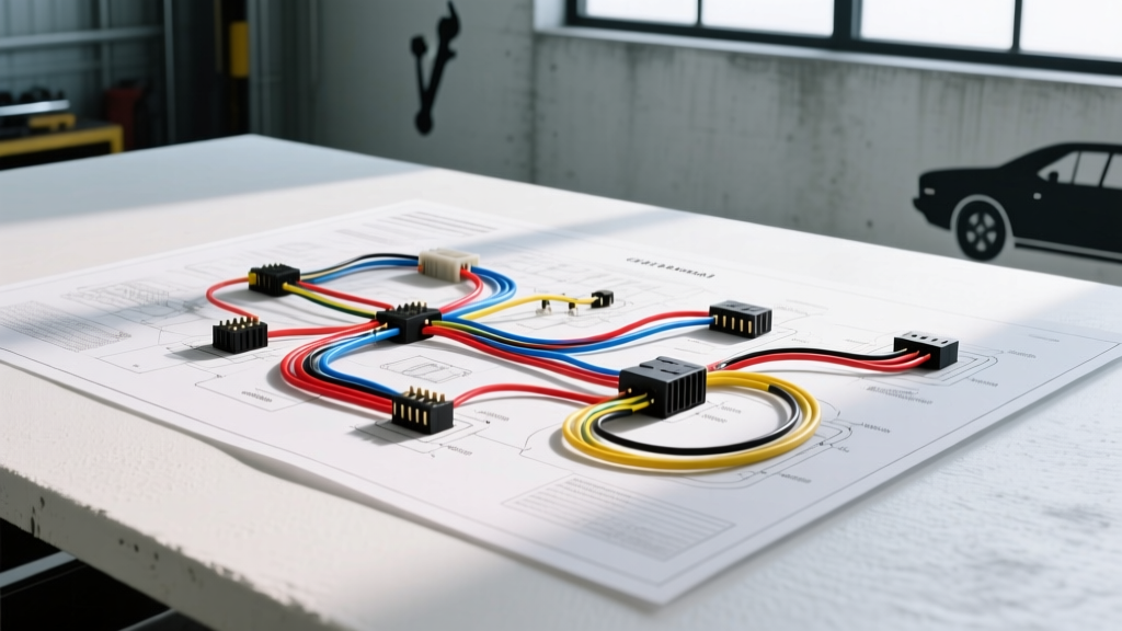
The Hidden Dangers of First-Generation F-Body Electrical Restorations
Restoring a classic muscle car is a rewarding endeavor, but the electrical system is where most projects stall—or worse, catch fire. When working on a first-generation F-body, relying on a generic small-block Chevy schematic instead of the exact 1968 Camaro wiring diagram is a critical error. The 1968 model year introduced specific changes to the forward lamp harness, the external voltage regulator pinouts, and the Rally Sport (RS) vacuum relay circuits that differ from the 1967 and 1969 models.
As an automotive electrical specialist, I frequently see restored Camaros suffer from melted bulkhead connectors, dim headlights, and alternator overcharge conditions. This guide breaks down the most common mistakes made when interpreting the 1968 Camaro schematics, alongside critical safety warnings to protect both you and your investment.
Critical Safety Warnings Before You Splice
The Horn Relay 'Hot' Bus Bar
Unlike modern vehicles that route all main power through a centralized fuse box, the 1968 Camaro utilizes the horn relay—mounted on the driver-side inner fender—as a primary power distribution junction. The heavy 10 AWG red wire running from the battery to the horn relay is hot at all times, bypassing the ignition switch entirely. If you drop a wrench across this terminal and the chassis while the battery is connected, you will instantly weld the wrench and potentially ignite the engine bay. Always disconnect the negative battery terminal and isolate the positive cable before servicing the forward lamp harness.
Fusible Link Sizing and Fire Prevention
General Motors utilized fusible links in 1968 to protect the main harness from catastrophic shorts. A common and dangerous mistake is replacing a blown fusible link with a standard maxi-fuse or a piece of solid copper wire. According to SAE J1128 standards, a fusible link must be exactly four wire gauges smaller than the circuit it protects. For the 10 AWG main battery feed, you must use a 14 AWG fusible link (typically orange in color for GM applications). Using 12 AWG or 10 AWG wire defeats the purpose, turning your wiring harness into a heating element during a short circuit.
5 Common Mistakes When Reading the 1968 Camaro Wiring Diagram
Mistake 1: Misinterpreting the External Voltage Regulator Plug
The 1968 Camaro originally equipped with the 10DN alternator uses an external, mechanical voltage regulator mounted on the core support. The 4-pin connector is a frequent source of wiring errors. The terminals on the regulator are marked F, 2, 3, and 4, which correspond to specific wire colors:
- Terminal F (Field): Blue wire (18 AWG) - Connects to the alternator F terminal.
- Terminal 2 (Stator): White wire (18 AWG) - Connects to the alternator stator tap.
- Terminal 3 (Sense): Red wire (18 AWG) - Reads battery voltage at the horn relay bus.
- Terminal 4 (Ignition): Brown wire (18 AWG) - Switched 12V from the ignition switch.
The Error: Many restorers swap to a modern 12SI internally regulated '1-wire' alternator but leave the old 4-pin plug dangling and exposed in the engine bay. Because the original Red (Sense) and Brown (Ignition) wires are tied to live circuits, an exposed plug can easily short against the chassis, melting the firewall bulkhead. Always cap and heat-shrink the abandoned OEM regulator plug.
Mistake 2: Overlooking the Forward Lamp Ground Paths
The 1968 forward lamp harness does not use dedicated ground wires for the headlights. Instead, it relies on the physical connection between the headlight bezels, the core support, and the engine block. If you have freshly painted your core support or used powder-coated headlight buckets, you have created an electrical insulator. This causes 'backfeed,' where turning on the headlights causes the parking lights and dash cluster to glow dimly. You must scrape away paint at the ground eyelets and use a star washer to ensure bare metal-to-metal contact.
Mistake 3: Upgrading the Alternator Without Upgrading the Feed
The factory 1968 wiring diagram specifies a 10 AWG main feed wire from the horn relay to the firewall junction block, designed for the stock 35-amp or 42-amp alternator. If you install a modern 100-amp+ 1-wire alternator to run electric fans and EFI, that 10 AWG wire will overheat and melt the bulkhead connector. You must run a new 6 AWG or 4 AWG XLPE wire directly from the alternator output post to the battery positive, bypassing the factory horn relay bus entirely for high-amperage applications.
Mistake 4: Confusing RS and Standard Headlight Harnesses
The Rally Sport (RS) package featured hidden headlights operated by a vacuum system. The 1968 RS wiring diagram includes specific relays and limit switches located behind the front bumper to control the vacuum solenoids. A standard headlight harness lacks the necessary 14 AWG purple and yellow wires that trigger the vacuum relays. Attempting to splice RS components into a standard harness without upgrading the switch contacts will melt the headlight switch rheostat.
Mistake 5: Ignoring Bulkhead Connector Pin Tension
The main engine-to-body bulkhead connector is a multi-pin block that passes through the firewall. Over 50 years, the brass female terminals lose their spring tension. Simply plugging in a reproduction harness without checking pin drag will result in high resistance. High resistance generates heat, which melts the plastic connector shell. Use a small pick to gently squeeze the female tangs inward to restore tension, and apply a dielectric grease like DeoxIT to prevent moisture ingress.
OEM Wire Color Codes & Gauge Specifications
When tracing faults or building a custom harness, cross-reference your work against these factory specifications derived from the Camaro Research Group and original GM Assembly Instruction Manuals (AIM).
| Circuit Function | OEM Wire Color | AWG Size | Connector / Termination |
|---|---|---|---|
| Battery to Horn Relay Feed | Red | 10 | Ring Terminal (5/16') |
| Horn Relay to Firewall Junction | Red | 10 | Bulkhead Pin / Ring |
| Headlight Switch to Dimmer | Red | 12 | Floor Dimmer Plug |
| Dimmer to Low Beam (Outer) | Tan | 12 | Headlight Bucket Plug |
| Dimmer to High Beam (Inner/Outer) | Green | 12 | Headlight Bucket Plug |
| High Beam Indicator Lamp | Green (w/ Black stripe) | 18 | PC Board Socket |
| Parking Lights Feed | Brown | 16 | Weather-Pack Style |
| Alternator Field (Regulator F) | Blue | 18 | Delco 2-Pin Plug |
| Ignition Switch to Regulator (Term 4) | Brown | 18 | Regulator 4-Pin Plug |
Troubleshooting Decision Tree: Dim or Flickering Headlights
If your 1968 Camaro suffers from dim headlights that flicker at idle, follow this diagnostic path before replacing the alternator:
- Measure Voltage at the Battery: With the engine at 1,500 RPM and headlights ON, you should see 13.8V - 14.2V. If lower, check the alternator belt tension and the external regulator ground.
- Measure Voltage at the Headlight Plug: Probe the Tan (Low) or Green (High) wire at the back of the headlight bulb. If there is a voltage drop of more than 0.5V compared to the battery, you have harness resistance.
- Check the Bulkhead Connector: Feel the plastic firewall bulkhead connector while the lights are on. If it is warm to the touch, the pins are corroded or loose, creating a bottleneck.
- Inspect the Floor Dimmer Switch: The 1968 floor-mounted dimmer switch is exposed to moisture and road debris. The internal copper contacts frequently pit and corrode, causing a massive voltage drop. Bypass the switch temporarily with a jumper wire to confirm.
Modern Wire Insulation vs. OEM Cloth
Original 1968 Camaro wiring featured PVC insulation, often wrapped in cloth tape or loom for abrasion resistance. PVC becomes brittle over time, especially in high-heat engine bays, leading to cracked insulation and dead shorts. When repairing or fabricating sections of your harness, never use cheap PVC wire from a hardware store. Always specify GXL or TXL cross-linked polyethylene (XLPE) wire. GXL features a thicker insulation wall for rugged environments, while TXL offers a thinner wall for tight spaces, both rated for continuous under-hood temperatures up to 125°C (257°F), far exceeding the capabilities of 1960s PVC.
Final Thoughts on Safety and Accuracy
The 1968 Camaro wiring diagram is not just a suggestion; it is the blueprint for the vehicle's nervous system. Deviating from OEM wire gauges, ignoring ground paths, or failing to properly terminate high-amperage circuits will result in electrical gremlins at best, and a total vehicle loss at worst. Take the time to verify every pinout, crimp your terminals with the correct ratcheting dies, and respect the unfused nature of the main battery feeds. For further technical documentation and factory build sheets, always consult the NHTSA archives and dedicated first-generation F-body restoration manuals.