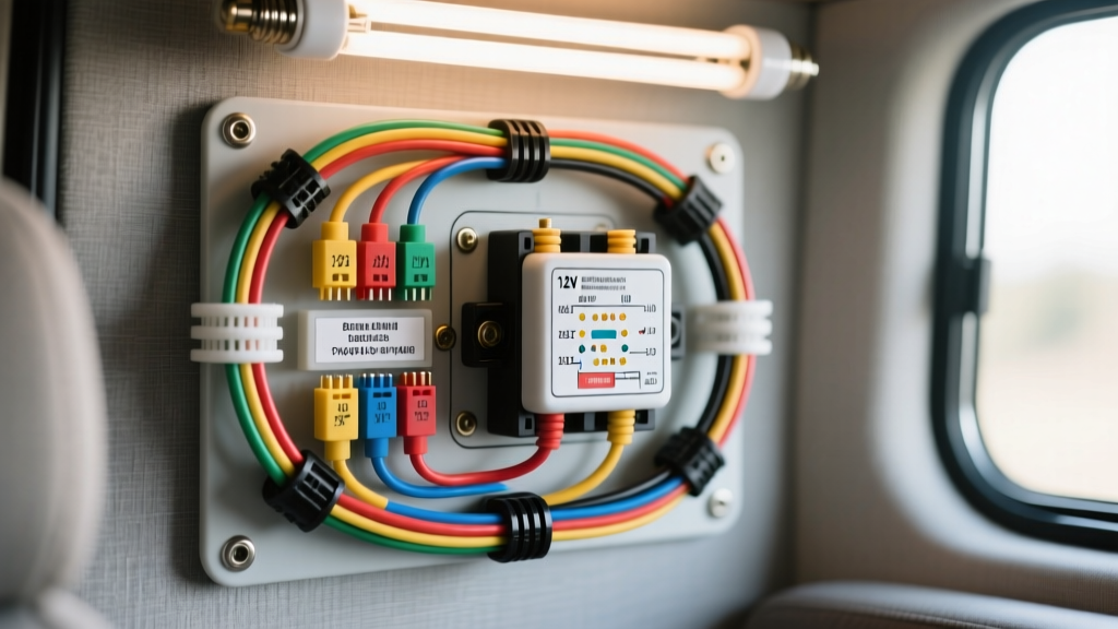
Introduction to 12V DC Fluorescent Systems in Mobile Platforms
Integrating interior lighting into custom camper vans, overland expedition trucks, and mobile utility service bodies requires a deep understanding of 12V DC electrical architecture. While modern builds heavily favor LED lighting, many existing platforms and specialized utility truck upfits still rely on 12V DC fluorescent fixtures. These fixtures demand specific ballast configurations, robust voltage regulation, and precise wire gauge sizing to operate reliably in high-vibration, high-temperature automotive environments. Whether you are repairing an existing 12V fluorescent circuit in a Ford Transit utility upfit or planning a comprehensive LED bypass modification, understanding the foundational wiring diagram of a fluorescent lamp designed for 12V DC applications is critical for a safe and efficient mobile electrical system.
Unlike standard 120V AC residential fluorescent lamps, 12V DC fluorescent fixtures utilize a specialized electronic ballast that acts as a DC-DC boost converter. This ballast steps up the vehicle's 12V-14.4V nominal system voltage to the high-voltage, high-frequency AC required to strike the mercury-argon arc inside the T8 or T12 glass tube. Because of this conversion process, the wiring schematics, pinouts, and failure modes differ significantly from standard automotive lighting circuits.
Core Components: The 12V DC Electronic Ballast
The heart of any 12V fluorescent fixture is the rapid-start electronic ballast. In mobile applications, these ballasts are engineered to handle the harsh electrical noise and voltage spikes inherent to vehicle alternators. According to SAE J1128 standards for low-tension primary cable, the wiring feeding these ballasts must be rated for high-temperature automotive environments and exhibit excellent resistance to abrasion and chemical exposure.
A standard 12V DC fluorescent ballast features a primary input side (connecting to the vehicle's 12V power and ground) and a secondary output side (connecting to the lamp's tombstone sockets). The primary side requires strict adherence to AWG sizing and overcurrent protection, while the secondary side requires precise high-voltage wiring to the lamp pins.
Standard 12V Ballast Pinout & Wire Color Codes
When mapping the wiring diagram of a fluorescent lamp fixture for a 12V system, you will typically encounter a 4-pin or 6-pin primary harness. Below is the standard pinout configuration for a dual-lamp 12V DC rapid-start ballast commonly found in RV and utility truck applications.
| Pin / Wire | Standard RV/Truck Wire Color | AWG Size | Function & Connection Point |
|---|---|---|---|
| Pin 1 (Input) | Red (or Yellow for 12V+ switched) | 14 AWG | 12V+ DC Power from Fuse Block / Relay |
| Pin 2 (Input) | White (or Black) | 14 AWG | 12V- DC Chassis Ground or Bus Bar |
| Pin 3 (Output) | Blue | 18 AWG (Ballast Lead) | High-Frequency AC to Lamp 1 (Pin 1 & 2) |
| Pin 4 (Output) | Red | 18 AWG (Ballast Lead) | High-Frequency AC to Lamp 1 (Pin 3 & 4) |
| Pin 5 (Output) | Yellow | 18 AWG (Ballast Lead) | High-Frequency AC to Lamp 2 (Pin 1 & 2) |
| Pin 6 (Output) | Black | 18 AWG (Ballast Lead) | High-Frequency AC to Lamp 2 (Pin 3 & 4) |
Executing the Wiring Diagram of a Fluorescent Lamp
Proper execution of the 12V fluorescent wiring diagram requires marine-grade or RVIA-certified materials. The Recreation Vehicle Industry Association (RVIA) mandates the use of stranded, tinned copper wire for all 12V DC interior lighting circuits to prevent galvanic corrosion and strand breakage caused by vehicular vibration.
- Overcurrent Protection: Always install an ATC or MAXI blade fuse at the power source. For a single 32W 12V fluorescent fixture (drawing approximately 2.6 Amps at 12V), a 5A fuse is appropriate. For a trunk line feeding multiple fixtures, calculate the total amperage and size the fuse and wire gauge according to Blue Sea Systems circuit protection guidelines.
- Primary Wiring (14 AWG): Route the 14 AWG Red (12V+) and White (12V-) wires from the fused distribution block to the ballast. Use adhesive-lined heat shrink butt connectors (Mil-Spec M22520) rather than vinyl crimps to ensure a moisture-proof, vibration-resistant seal.
- Grounding Protocol: Do not rely on sheet metal screws for grounding fluorescent ballasts. The high-frequency nature of the electronic ballast can cause RF interference and poor grounding through painted chassis metal. Run a dedicated 14 AWG ground wire directly to a centralized, cleaned copper bus bar tied to the vehicle's main negative battery terminal.
- Secondary Wiring (Tombstone Connections): Connect the ballast's 18 AWG output leads to the non-shunted tombstone sockets. Ensure the push-in terminal springs are fully seated; loose connections on the high-frequency AC side will cause arcing, melting the plastic socket housing.
Voltage Drop Calculations for Long-Run Vehicle Wiring
A frequent error in camper van and utility truck upfits is undersizing the wire gauge for long cable runs. Fluorescent ballasts are highly sensitive to voltage drops; if the voltage at the ballast input falls below 10.5V, the DC-DC boost converter will fail to strike the arc, resulting in flickering or complete failure to illuminate.
To calculate voltage drop, use the following formula: VD = (2 × L × I × R) / 1000
- L = Total wire length in feet (Positive + Negative run)
- I = Current draw in Amps
- R = Wire resistance per 1,000 feet (14 AWG copper = ~2.525 Ω)
Real-World Scenario: You are wiring a trunk line to feed four 32W fluorescent lamps in a 30-foot Sprinter van. Total draw is roughly 10.5 Amps. The one-way cable run from the fuse box to the last fixture is 25 feet (Total L = 50 feet).VD = (2 × 25 × 10.5 × 2.525) / 1000 = 1.32 Volts
A 1.32V drop on a 12V system represents an 11% voltage drop, which far exceeds the acceptable 3% threshold for sensitive electronics. The Fix: Upgrade the trunk line to 8 AWG wire (R = 0.628 Ω/kft), which reduces the drop to 0.33V (2.7%), ensuring reliable ballast ignition.
Common Failure Modes in Automotive Fluorescent Circuits
When troubleshooting an existing 12V fluorescent layout, be aware of these platform-specific failure modes:
- Load Dump Ballast Failure: When a vehicle's alternator disengages suddenly, it can send voltage spikes exceeding 60V through the 12V system. Cheap, non-automotive-grade 12V ballasts lack internal TVS (Transient Voltage Suppression) diodes, leading to immediate capacitor blowouts. Always source ballasts specifically rated for automotive load-dump survival.
- Tombstone Socket Melting: Caused by high-resistance connections at the tube pins. As the socket heats up, the internal spring tension relaxes, worsening the resistance and eventually melting the polycarbonate housing. Replace melted sockets with heavy-duty ceramic or high-temp PBT tombstones.
- RF Interference with Vehicle CAN Bus: Poorly shielded 12V fluorescent ballasts can emit electromagnetic interference (EMI) that disrupts sensitive CAN bus networks in modern trucks (e.g., Ford Transit, RAM ProMaster). Ensure ballast housings are grounded and keep input wiring routed away from CAN High/CAN Low twisted pairs.
Upgrade Modification: Ballast Bypass for 12V LED T8 Tubes
The most common modification project in modern RV and utility truck refurbishments is the ballast bypass. 12V DC fluorescent lamps are inefficient, generate excessive heat, and contain hazardous mercury. Upgrading to direct-drive 12V LED T8 tubes reduces amperage draw by up to 70%, eliminating voltage drop issues and extending the vehicle's auxiliary battery bank runtime.
Step-by-Step LED Rewiring Protocol
Most 12V DC LED T8 replacement tubes are single-ended direct-drive. This means they do not require a ballast; they require raw 12V DC polarity applied to one specific end of the tube.
- Disconnect Power: Remove the ATC fuse feeding the lighting circuit at the main distribution panel.
- Remove the Ballast: Cut the 14 AWG input wires and the 18 AWG output wires. Remove the heavy electronic ballast from the fixture housing to save weight and eliminate a potential point of failure.
- Identify Tombstone Types: Check the existing sockets. If they are non-shunted (the two wire insertion holes are electrically isolated), you must install a jumper wire between the two terminals on the "Live" end socket to ensure both pins on the LED tube receive power.
- Wire the Live End: Run the 14 AWG 12V+ (Red) wire directly to one of the tombstone sockets at the designated "Live" end of the fixture. Use a WAGO 221 lever nut or a properly crimped pigtail to connect the wire to the socket's 18 AWG lead.
- Wire the Ground End: Run the 14 AWG 12V- (White) wire directly to the tombstone socket at the opposite "Ground" end of the fixture.
- Cap Unused Wires: Securely cap any unused wires at the opposite ends of the tombstones with heat shrink to prevent short circuits against the metal fixture housing.
- Test and Install: Re-insert the fuse, verify polarity with a multimeter at the sockets (should read ~12.6V), and snap in the single-ended 12V LED T8 tubes, ensuring the "Live" label on the tube aligns with the 12V+ socket.
By executing this modification, you fundamentally alter the wiring diagram of the fluorescent lamp fixture, transforming it into a highly efficient, solid-state LED array perfectly suited for the rigorous demands of mobile automotive applications.