The Life-or-Death Reality of 12V CO Sensor Wiring
When installing a hardwired Carbon Monoxide (CO) detector in an RV, overland expedition vehicle, or enclosed marine cabin, the wiring is not just an electrical task—it is a life-safety system. A flawed co sensor wiring diagram implementation can result in a detector that fails to trigger during a lethal exhaust leak, or worse, suffers from chronic voltage drops that silently disable the unit. Unlike standard automotive accessories, CO sensors require dedicated, clean 12V DC power and meticulous grounding to prevent false alarms, microprocessor brownouts, and electrochemical cell degradation.
Carbon monoxide is an odorless, colorless gas produced by incomplete combustion in gas generators, diesel heaters, and vehicle exhaust systems. Because the margin for error is zero, understanding the exact pinouts, wire gauge requirements, and common DIY pitfalls is mandatory for any automotive electrician or DIY van-builder. This guide breaks down the critical safety warnings and technical specifications required to wire a 12V CO sensor correctly.
Standard 12V Hardwired CO Sensor Wiring Diagram Breakdown
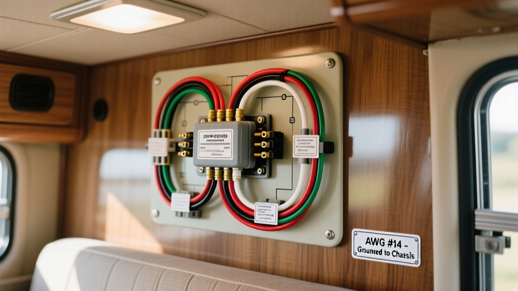
Most automotive and RV-grade hardwired carbon monoxide detectors (such as those manufactured by MTI Industries/Safe-T-Alert or First Alert) utilize a standardized 3-wire or 4-wire harness. The internal microprocessor continuously samples the ambient air using an electrochemical cell, which requires a stable voltage reference to calculate parts-per-million (PPM) accurately.
| Wire Color | Function | Connection Point | Technical Notes |
|---|---|---|---|
| Red | 12V+ Constant Power | Battery Positive (via dedicated fuse) | Must be unswitched. Sensor draws ~60mA-120mA continuously. |
| Black (or White) | 12V- Ground | Dedicated Chassis Ground or Battery Negative | Must be a clean, bare-metal ring terminal connection. |
| Yellow | Alarm Trigger / Signal Out | 12V Relay Coil or Alarm Panel Input | Outputs 12V+ or Ground when CO exceeds 70 PPM for 60+ mins. |
| Green | Fault / End-of-Life Signal | Diagnostic LED or Multiplex Node | Used on advanced units to indicate electrochemical cell failure. |
5 Fatal Mistakes in DIY CO Sensor Installations
Reviewing thousands of field installations and forensic electrical audits reveals a pattern of dangerous errors. Avoid these five critical mistakes when executing your co sensor wiring diagram.
1. Tapping into a Switched Ignition Circuit
The most common and deadly mistake is wiring the Red (12V+) wire to a switched ignition source or a cabin accessory switch. If the vehicle is parked, the engine is off, and the keys are removed, the CO sensor loses power. If a nearby diesel heater or idling neighbor's exhaust infiltrates the cabin while you sleep, the sensor will remain completely dead. Rule: The CO sensor must be wired directly to the house battery bank or a constant 12V+ bus bar, completely independent of the ignition switch.
2. Sharing a Ground with High-Draw Appliances
Daisy-chaining the CO sensor's Black ground wire to the same chassis stud used by a water pump, compressor fridge, or inverter is a recipe for disaster. When a high-draw appliance cycles on, it creates a momentary voltage drop and electromagnetic interference (EMI) on the ground plane. This "dirty ground" can cause the CO sensor's microprocessor to reset, trigger a false alarm, or temporarily blind the electrochemical cell. Always run a dedicated ground wire back to the main negative bus bar or a verified, isolated chassis ground point sanded down to bare metal.
3. Using Undersized or CCA Wire
While a CO sensor only draws roughly 100mA, using 22 AWG wire or Copper-Clad Aluminum (CCA) wire is a severe safety hazard. CCA wire is brittle, prone to breaking under automotive vibration, and has a higher resistance than pure copper. According to SAE J1128 standards for low-tension primary cable, you must use stranded, pure copper wire with automotive-grade insulation (TXL, GXL, or SXL) to withstand under-floor or cabin heat.
4. Ignoring Voltage Drop Over Long Runs
In large Class A motorhomes or expedition trailers, the distance from the battery bank to the cabin ceiling can exceed 25 feet. A standard 18 AWG wire over a 50-foot round-trip run will experience a voltage drop. If the voltage at the sensor drops below 10.5V during a low-battery state, the sensor may enter a low-voltage fault mode and disable the audible 85dB alarm. Always calculate voltage drop and upsize the wire for long runs.
5. Improper Sensor Placement Relative to Airflow
While not strictly a wiring error, wiring a sensor that is mounted incorrectly renders the electrical work moot. Carbon monoxide has a specific gravity of 0.968, making it slightly lighter than air, but it readily mixes with ambient cabin air. Do not wire and mount the sensor directly above a Propane/LPG detector (which must be near the floor), and keep it at least 5 feet away from cooking appliances to prevent false alarms from hydrogen gas emitted during battery charging or cooking.
Wire Gauge (AWG) and Overcurrent Protection Specs
Proper overcurrent protection is vital. A short circuit in the sensor wiring could cause an electrical fire. Because the sensor draws less than 0.15 Amps, a standard 15A automotive fuse will not blow before the 18 AWG wire melts. You must use appropriately sized fuses located within 7 inches of the power source.
| Total Wire Run (Round Trip) | Recommended Wire Gauge (AWG) | Wire Type | Required Fuse Size |
|---|---|---|---|
| 0 - 15 Feet | 18 AWG | TXL / GXL Stranded Copper | 2A Mini (ATM) Blade Fuse |
| 15 - 30 Feet | 16 AWG | TXL / GXL Stranded Copper | 3A ATO / ATC Blade Fuse |
| 30 - 50 Feet | 14 AWG | TXL / GXL Stranded Copper | 5A ATO / ATC Blade Fuse |
Advanced Integration: Relay Trigger Wiring for Cabin Exhaust Fans
For advanced overland builds and marine applications, a standalone audible alarm may not be enough to wake a sleeping occupant or ventilate the cabin automatically. By utilizing the Yellow (Alarm Trigger) wire on your co sensor wiring diagram, you can integrate the CO detector with a 12V roof exhaust fan or a smart-cabin relay board.
Bosch-Style 5-Pin Relay Wiring for Automatic Ventilation
To wire a standard ISO mini relay (Bosch style) that automatically triggers a 12V exhaust fan when CO is detected, follow this pinout configuration:
- Pin 86 (Relay Coil +): Connect to the CO Sensor Yellow (Alarm Output) wire.
- Pin 85 (Relay Coil -): Connect to a clean 12V- Chassis Ground.
- Pin 30 (Common Input): Connect to a dedicated 12V+ Constant source (fused at 10A for the fan).
- Pin 87 (Normally Open Output): Connect to the Positive (+) wire of the 12V Cabin Exhaust Fan.
- Pin 87a (Normally Closed): Leave unused and insulated.
Safety Warning: Ensure the exhaust fan you are triggering is rated for continuous duty and does not draw more current than the relay contacts can handle (typically 30A-40A). If the fan draws high current, use this relay to trigger a secondary high-amperage solenoid.
Troubleshooting Matrix: False Alarms and Power Failures
When a CO sensor chirps or fails to power on, DIYers often assume the unit is defective. In 80% of cases, the issue stems from poor wiring practices. Use this decision tree to diagnose the problem.
| Symptom | Probable Electrical Cause | Diagnostic Action & Fix |
|---|---|---|
| Sensor chirps every 60 seconds | Low Voltage / Voltage Drop | Measure voltage at the sensor pigtail. If below 11.5V, check for undersized AWG or corroded inline fuse holders. |
| False alarms when turning on inverter | EMI / Dirty Ground | Move the sensor ground wire away from the inverter ground bus. Use a dedicated star-washered chassis ground. |
| Sensor completely dead (No LED) | Blown Fuse or Switched Power | Verify 12V+ at the Red wire with a multimeter. Ensure the circuit is not tied to a master cabin kill-switch. |
| Alarm triggers during battery charging | Hydrogen Gas Interference | Electrochemical CO cells can cross-react with hydrogen off-gassing from flooded lead-acid batteries. Relocate sensor away from battery boxes. |
Authoritative Safety Standards & Compliance
When designing your vehicle's electrical system, always defer to established life-safety codes. The NFPA 1192 Standard on Recreational Vehicles explicitly mandates the placement, power sourcing, and testing protocols for carbon monoxide detection systems in mobile environments. Furthermore, compliance with RVIA (Recreational Vehicle Industry Association) guidelines ensures that your wiring methods meet the stringent fire and electrical safety inspections required for modern motorhomes and travel trailers.
Always consult the specific OEM installation manual for your sensor model, such as the MTI Industries Safe-T-Alert documentation, as pinouts and alarm trigger voltages can vary slightly between manufacturers. Never bypass the internal fault-detection circuitry, and replace all electrochemical CO sensors every 5 to 7 years, regardless of their electrical condition, as the chemical cells naturally degrade over time.