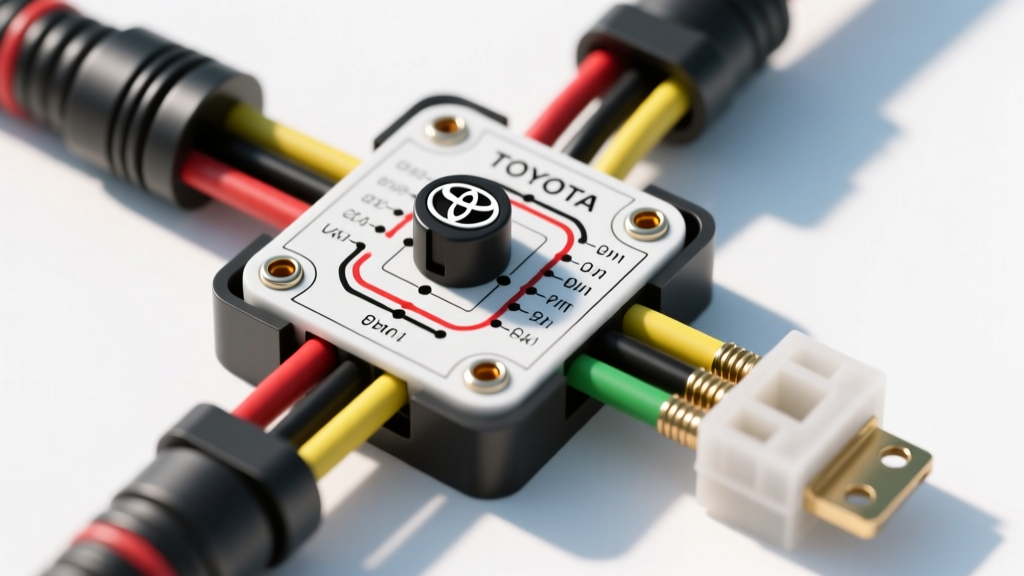
Understanding Toyota Ignition Switch Architecture
When diagnosing a no-crank, no-start, or intermittent electrical failure on late-1990s to mid-2000s Toyota platforms (such as the Tacoma, Camry, and 4Runner), the electrical ignition switch is a primary suspect. It is critical to differentiate between the mechanical lock cylinder (where the key is inserted) and the electrical ignition switch (the multi-pin component bolted to the steering column that the cylinder actuates). Over time, the internal brass contacts within the electrical switch suffer from fretting corrosion, leading to high resistance, voltage drop, and in severe cases, melted wiring harness pigtails.
This advanced technical guide provides a comprehensive Toyota ignition switch wiring diagram, OEM wire color codes, and a safe, actionable procedure for creating an emergency diagnostic bypass harness. Note: This procedure is intended for off-road, race vehicle, or emergency diagnostic use on vehicles you own. Bypassing factory security systems for theft is illegal.
Safety, Immobilizer Constraints, and Legal Disclaimer
Before attempting any bypass ignition key Toyota ignition switch wiring diagram procedure, you must account for the factory immobilizer system. Starting in 1998, most Toyota models were equipped with an Engine Immobilizer System utilizing a transponder chip embedded in the key head.
- The Transponder Ring (Pickup Coil): Located around the lock cylinder, this ring reads the transponder chip and sends a signal to the Immobilizer Amplifier, which then communicates via serial data to the ECU.
- Bypass Limitation: Jumping the B+ to IG1 and ST1 circuits will engage the starter and fuel pump, but the ECU will immediately cut spark and injector pulses if it does not detect the correct transponder signature.
- Race/Off-Road Workaround: For dedicated track vehicles, the immobilizer amplifier can be bypassed using an ECU flash or a standalone immobilizer emulator. Alternatively, the transponder ring can be carefully removed from the column and zip-tied directly to the transponder key head near the ECU to satisfy the security handshake.
Toyota 8-Pin Ignition Switch Pinout & Wire Color Matrix
The standard Toyota 8-pin ignition switch connector (commonly found on the 1996-2004 Tacoma and 1997-2001 Camry) handles high-amperage battery feeds and low-amperage switched signals. The following matrix details the OEM specifications based on factory service documentation and Toyota Technical Information System (TIS) schematics.
| Pin | Circuit Function | OEM Wire Color | AWG Size | Circuit Description & Load |
|---|---|---|---|---|
| 1 | B+ (Main) | White w/ Red Stripe | 10 AWG | Constant 12V from Battery. Feeds the switch bus bar. |
| 2 | B+ (Secondary) | White | 10 AWG | Constant 12V. Redundant feed for high-load distribution. |
| 3 | ACC | Gray | 14 AWG | Powers radio, wipers, and accessories in ACC and ON positions. |
| 4 | IG1 | Black w/ Red Stripe | 14 AWG | Main ECU power, Fuel Pump relay, Dashboard warning lights. |
| 5 | IG2 | Black w/ Yellow Stripe | 14 AWG | Powers accessories that require voltage during the CRANK cycle. |
| 6 | ST1 | Black w/ White Stripe | 14 AWG | Starter signal. Energizes the Starter Cut Relay / Neutral Safety Switch. |
| 7 | ST2 | Black | 14 AWG | De-energizes A/C compressor and rear defogger during cranking. |
| 8 | ACC2 | Gray w/ White Stripe | 14 AWG | Secondary accessory feed (e.g., power windows, cigarette lighter). |
Circuit Definitions & Switch Positions
Understanding the internal mechanical wiper plates of the switch is vital for replicating its behavior with a bypass harness:
- OFF/LOCK: Only B+ pins (1 & 2) are live. All switched circuits are open.
- ACC: B+ connects to ACC (3) and ACC2 (8).
- ON (IG): B+ connects to ACC, ACC2, IG1 (4), and IG2 (5).
- START (Crank): B+ connects to IG1, IG2, ST1 (6), and ST2 (7). Note: ACC and ACC2 are intentionally dropped during cranking to maximize battery voltage for the starter motor and ECU.
Step-by-Step Diagnostic & Emergency Bypass Procedure
If your vehicle exhibits a melted pigtail or fails to crank, do not immediately rip out the wiring. Follow this diagnostic sequence to verify the failure and construct a safe bypass harness using SAE J1128 Low Tension Primary Cable Standard compliant wire.
Step 1: Harness Access and Voltage Drop Testing
Remove the lower steering column shroud to access the 8-pin ignition switch connector. Before unplugging, perform a voltage drop test across the switch contacts while an assistant holds the key in the START position.
- Set your digital multimeter to DC Volts.
- Place the positive probe on the B+ wire (Pin 1) at the harness side.
- Place the negative probe on the ST1 wire (Pin 6) at the harness side.
- Crank the engine. A healthy switch will show a voltage drop of less than 0.15V. A drop exceeding 0.5V indicates severe internal contact resistance, confirming the switch is the culprit.
Step 2: Creating the Bypass Jumper Harness
To bypass the ignition key Toyota ignition switch wiring diagram for a race application or emergency extraction, you must build a jumper harness that replicates the switch's logic. Never simply twist wires together; the high current draw of the fuel pump and ECU will melt twisted connections, creating a severe fire hazard.
- Main Power Feed: Splice into the 10 AWG White/Red (Pin 1) wire using a solder-seal butt connector. Run this to a heavy-duty 50A marine-grade toggle switch.
- IG1 & IG2 Distribution: From the output of the main toggle switch, use 14 AWG wire to jump to both the Black/Red (IG1, Pin 4) and Black/Yellow (IG2, Pin 5) wires. This powers the ECU and fuel system.
- Starter Engagement (ST1): Wire a momentary push-button switch (rated for at least 15A) to the Black/White wire (ST1, Pin 6). This will engage the starter relay.
Expert Tip: According to data shared on the International Automotive Technicians Network (iATN), many technicians forget to wire IG2. If IG2 is not powered during cranking, the ECU may not register the RPM signal correctly, resulting in a crank-no-start condition.
Step 3: Addressing the Melted Pigtail Failure Mode
On 3.4L V6 Tacomas and 3.0L V6 Camrys, it is incredibly common to find the 10 AWG White/Red and White wires melted into the plastic connector housing. This occurs because the factory brass contacts oxidize over 15+ years of use. The oxidation increases resistance (R). According to Joule's Law (P = I²R), as resistance increases under the heavy amperage load of the fuel pump and HVAC blower, heat generation spikes exponentially, melting the plastic housing.
The Fix: If the pigtail is melted, you must cut the harness back at least 6 inches to reach clean, unoxidized copper. Solder in a replacement OEM pigtail (available via dealerships) or use Deutsch DT connectors to create a serviceable, moisture-proof junction. Do not rely on crimp connectors in the steering column, as vibration will cause them to work loose over time.
Summary of Bypass Logic
Successfully executing a bypass ignition key Toyota ignition switch wiring diagram requires respecting the OEM circuit architecture. By isolating the high-amperage B+ feeds from the low-amperage signal wires, utilizing proper 10 AWG and 14 AWG cabling, and accounting for the immobilizer transponder ring, you can safely restore power to a stranded vehicle or build a reliable ignition system for a dedicated off-road rig. Always prioritize solder-seal terminations and inline ANL fuses to protect your custom wiring harness from catastrophic short circuits.