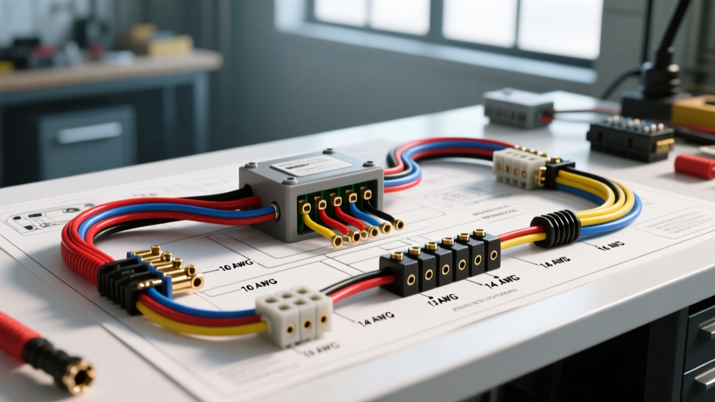
The Automotive DC Breaker Box vs. Residential AC Panels
When off-grid enthusiasts and commercial fleet technicians search for a wiring diagram for breaker box installations, they frequently encounter residential 120V/240V AC schematics. Applying household AC breaker logic to a 12V or 24V DC automotive environment is a critical error that leads to severe voltage drop, thermal fires, and destroyed sensitive ECU modules. Automotive DC breaker boxes—often configured as centralized power distribution panels or auxiliary busbar enclosures—require specific overcurrent protection devices (OCPDs) rated for DC voltage arcs, which sustain longer and burn hotter than AC arcs.
This complete wiring diagram walkthrough details the proper architecture, wire sizing, and physical execution of a 12V DC breaker box for overland trucks, RVs, and expedition SUVs. We will cover main feed integration, branch circuit routing, and the critical relay pinouts required to prevent parasitic battery drain.
Core Components of the 12V DC Distribution Panel
Before tracing the wiring diagram, you must select the correct hardware. A proper mobile DC breaker box relies on three primary components:
- Tinned Copper Busbars: Unlike brass, tinned copper resists galvanic corrosion when paired with copper ring terminals in high-humidity or marine environments.
- Type III Manual Reset Breakers: For high-amperage circuits (winches, DC-DC chargers, inverters), manual reset breakers are mandatory. According to NFPA 70 / NEC Article 551 (RV and Mobile DC Systems), main battery feeds and high-amp accessory circuits must not auto-reset, as an auto-resetting breaker on a shorted winch solenoid can cause a continuous thermal fire loop.
- MRBF / MIDI Fuses: Used for the absolute main battery disconnect before the power ever reaches the breaker box.
Step-by-Step Wiring Diagram Walkthrough
Phase 1: The Main Feed and VSR Integration
The foundation of any auxiliary breaker box is the main feed from the vehicle's starting battery or secondary deep-cycle house battery. This circuit must bypass the vehicle's factory fuse panel to handle the massive current draw of off-grid accessories.
- Battery to MRBF Fuse: Run 2/0 AWG SAE J1128 TYPE SGT battery cable from the positive battery post directly to a Marine Rated Battery Fuse (MRBF) mounted on the terminal. This provides catastrophic short-circuit protection within inches of the power source.
- VSR (Voltage Sensitive Relay): From the MRBF, route the 2/0 AWG cable to the input stud of a dual-sense VSR or a smart DC-DC isolator. This ensures the auxiliary breaker box only receives power when the alternator is actively charging (typically above 13.2V).
- VSR to Breaker Box Main Lug: Step down to 4 AWG GXL cross-linked wire for the run from the VSR output to the main positive busbar of your DC breaker box. GXL wire features a thin, high-temp insulation jacket rated for 125°C, making it ideal for routing through the firewall or under-hood engine bays where ambient temperatures exceed standard PVC limits.
Phase 2: High-Amperage Branch Circuit Wiring
From the main positive busbar, power is distributed to individual Type III breakers for heavy loads. Let's map out a 60A ARB fridge compressor and a 120A inverter circuit.
- The 120A Inverter Circuit: Connect a 4 AWG red wire from the main busbar to the "BAT" side of a 150A Type III breaker. From the "AUX" side of the breaker, run 2 AWG wire directly to the inverter's positive terminal. The massive gauge is required to mitigate voltage drop over the typical 6-to-10-foot run to the rear cargo area.
- The Fridge/Compressor Circuit: Run 8 AWG red wire from the main busbar to a 60A breaker, then 8 AWG to an Anderson Powerpole connector. Anderson connectors allow for modular disconnects when removing the fridge for vehicle cleaning or maintenance.
Phase 3: Ignition-Switched Relay Integration (Bosch-Style 4-Pin)
To prevent parasitic draw when the vehicle is parked, the secondary "accessory" breaker box bus must be triggered via a heavy-duty relay. This ensures that light bars, air compressors, and auxiliary lighting only receive power when the key is in the "ON" position. Use a standard Bosch-style 4-pin relay rated for 40A minimum, wired as follows:
- Pin 86 (Coil +): Connect to an ignition-switched 12V+ source (e.g., a 10A fuse tapped from the factory fuse panel using an add-a-circuit).
- Pin 85 (Coil -): Connect to a dedicated, clean chassis ground using a 10 AWG black wire and a ring terminal.
- Pin 30 (Common): Connect to the constant 12V+ output from the main DC breaker box busbar via a 30A inline blade fuse.
- Pin 87 (Normally Open): Connect to the input stud of the auxiliary/switched breaker box busbar. When the ignition turns on, the coil energizes, bridging Pin 30 to Pin 87 and waking up the accessory panel.
AWG Wire Sizing and Breaker Specification Chart
Proper wire sizing is dictated by the SAE J1128 Standard for Low-Tension Primary Cable and the maximum allowable voltage drop (typically 3% for sensitive electronics, 10% for resistive loads like lighting). Use this reference chart for standard 12V DC breaker box branch circuits assuming a 15-foot total round-trip wire length:
| Circuit Application | Max Continuous Load | Required AWG Size | Breaker Rating | Standard Wire Color |
|---|---|---|---|---|
| LED Light Bar (Relay Trigger) | 5 Amps | 16 AWG | 10A (Blade Fuse) | Yellow (Switched) |
| 12V Water Pump | 12 Amps | 12 AWG | 15A (Type I Auto) | Red (Constant) |
| Portable Air Compressor | 30 Amps | 8 AWG | 40A (Type III Manual) | Red (Constant) |
| DC-DC Battery Charger | 40 Amps | 6 AWG | 50A (Type III Manual) | Red (Constant) |
| Main Panel Feed (VSR) | 120 Amps | 4 AWG (or 2 AWG) | 150A (MIDI Fuse) | Red (Main Battery) |
Terminal Crimping and Torque Specifications
A wiring diagram is only as reliable as its physical terminations. The most common failure mode in mobile breaker boxes is high-resistance connections caused by improper crimping or incorrect torque.
- Crimp Tooling: Never use hammer-style crimpers or pliers for 8 AWG and larger wire. Use a hexagonal indent crimp tool (such as the Knipex 97 62 34) to cold-weld the copper strands to the barrel. This ensures a gas-tight seal that prevents internal oxidation.
- Heat Shrink: Always use dual-wall, adhesive-lined heat shrink with a 3:1 shrink ratio. When heated, the inner meltable adhesive layer forces out air and creates a waterproof barrier, preventing the "green fuzz" copper corrosion that plagues off-road vehicles.
- Torque Specs: According to Blue Sea Systems Circuit Protection Guidelines, over-torquing brass nuts on busbars will strip the threads and destroy the connection. For standard M8 (5/16") brass studs, torque to exactly 50 in-lbs. For 1/4" stainless steel studs with brass nuts, do not exceed 120 in-lbs. Always apply a conductive anti-oxidant paste like NO-OX-ID A-Special to the threads and terminal faces before tightening.
Troubleshooting Nuisance Tripping and Voltage Drop
DC breaker boxes in mobile environments face extreme vibration, dust ingress, and thermal cycling. Use this diagnostic decision tree to resolve common distribution panel failures:
- Symptom: Main 150A MIDI breaker trips intermittently during high-load inverter use.
Cause: Voltage drop across undersized feeder cables causing the inverter to pull higher amperage to compensate for low voltage, or thermal derating of the breaker in a hot engine bay.
Fix: Upgrade main feed to 1/0 AWG SGT cable. Relocate the primary breaker box to the climate-controlled cabin if ambient under-hood temps exceed 185°F (85°C). - Symptom: Accessory breaker (e.g., 30A fridge circuit) casing feels hot to the touch.
Cause: Loose terminal crimp creating high resistance, or stranded wire splaying outside the crimp barrel causing a localized bottleneck.
Fix: Cut and re-crimp using a proper hexagonal die. Verify terminal torque to 50 in-lbs. Ensure the wire gauge matches the barrel size exactly (do not fold wire back on itself to fill a loose barrel). - Symptom: Severe galvanic corrosion on busbar studs and nuts.
Cause: Electrolytic reaction between dissimilar metals (e.g., copper ring terminals and aluminum busbars), exacerbated by moisture and road salt.
Fix: Replace aluminum busbars with tinned copper. Clean all existing terminals with a brass wire brush, apply conductive anti-oxidant grease, and seal the entire breaker box enclosure with a silicone gasket.
Final System Validation
Once the physical wiring is complete, do not simply flip the switches. Use a digital multimeter to perform a static voltage drop test across every breaker terminal while under load. A healthy connection should show less than 0.05V drop across the breaker itself. Finally, label every circuit on the breaker box faceplate using a thermal-transfer printer. Faded sharpie labels are useless when troubleshooting a dead fridge at 2:00 AM on a remote trail. By adhering to these automotive-specific DC standards, your breaker box will provide reliable, fire-safe power distribution for years of expedition travel.