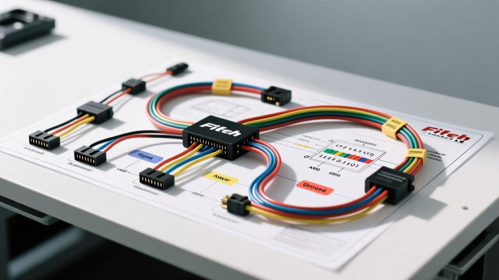
Introduction to FiTech Ultimate LS Harness Architecture
The FiTech Ultimate LS EFI system (commonly kit 550-012 and its variants) represents a highly efficient, plug-and-play fuel injection solution for GM LS engine swaps. However, the term "plug-and-play" only applies if the underlying chassis wiring, power distribution, and sensor grounding meet strict automotive electrical specifications. This technical reference provides the definitive FiTech Ultimate LS wiring diagram logic, ECU pinout configurations, and wire gauge requirements. Whether you are wiring a 4.8L LR4 truck engine or a 6.2L L92 aluminum block, understanding the exact AWG ratings, wire color codes, and pin assignments is critical to preventing ECU damage, injector misfires, and wideband oxygen sensor lag.
Main Power and Chassis Ground Architecture
Before connecting the main ECU harness, the primary power and ground architecture must be established. The FiTech ECU requires clean, unswitched battery voltage for memory retention and a robust switched 12V source for ECU wake-up and cranking stability.
- Main Battery Feed (ECU Pin A1): Requires 8 AWG stranded copper wire (meeting SAE J1128 GXL or TXL standards). This circuit must be protected by a 60-amp marine-grade circuit breaker or MaxiFuse located within 18 inches of the battery positive terminal.
- Main ECU Ground (ECU Pin A2 & A3): Requires 8 AWG wire. Both ground wires must terminate directly to the engine block or cylinder head using a copper ring terminal, a star washer to bite through paint and corrosion, and torqued to 18 lb-ft. Never ground the ECU to the chassis firewall, intake manifold, or accessory brackets.
- Switched 12V Ignition (ECU Pin B4): Requires 14 AWG wire. Sourced from the ignition switch "Run/Start" circuit. This wire must read within 0.2V of battery voltage during cranking. If voltage drops below 10.5V during cranking, the ECU will shut down injector drivers. To fix this, install a standard 30A Bosch-style relay triggered by the ignition switch to feed a dedicated 12 AWG switched line directly to the ECU.
FiTech Ultimate LS ECU Pinout Reference Table
The main ECU harness terminates into a sealed multi-pin connector. Below is the critical pinout reference for the primary engine functions. Note that while wire colors may vary slightly between harness manufacturing revisions, the pin assignments and functional logic remain constant.
| Pin Number | Function | Wire Color | AWG Size | Technical Notes |
|---|---|---|---|---|
| A1 | Main Battery 12V+ | Red | 8 AWG | Constant power, fused at 60A max |
| A2 | Main ECU Ground | Black | 8 AWG | Engine block ground, star washer |
| A3 | Secondary Ground | Black | 8 AWG | Engine block ground, star washer |
| B4 | Switched 12V Ignition | Pink | 14 AWG | Run/Start circuit, min 10.5V cranking |
| C1 | Injector 1 (Bank 1) | Yellow | 18 AWG | USCAR connector, PWM controlled |
| C2 | Injector 2 (Bank 1) | Yellow | 18 AWG | USCAR connector, PWM controlled |
| D1 | Coil 1 Signal | White | 18 AWG | LS Truck coil pin 4 (IGT) |
| D2 | Coil 2 Signal | White | 18 AWG | LS Truck coil pin 4 (IGT) |
| E1 | MAP Sensor Signal | Green | 22 AWG | Shielded wire, 5V to 0.5V range |
| E2 | MAP Sensor 5V Ref | Orange | 22 AWG | Do not share with TPS 5V ref |
| E3 | MAP Sensor Ground | Black/White | 22 AWG | Dedicated sensor ground to ECU |
| F1 | Wideband O2 Signal | Blue | 22 AWG | Bosch LSU 4.9 harness specific |
| F2 | Wideband O2 Heater | Red/White | 14 AWG | Fused at 15A, relay recommended |
| G4 | Fuel Pump Relay Ground | Blue | 18 AWG | Low-side driver, max 2A draw |
| G5 | Cooling Fan Relay Ground | Green/White | 18 AWG | Low-side driver, requires flyback diode |
Sensor and Actuator Wiring Specifications
Proper sensor wiring is the most common failure point in aftermarket LS swaps. The FiTech Ultimate LS utilizes standard GM-style sensors, but harness routing and shielding dictate signal integrity.
Manifold Absolute Pressure (MAP)
The 1-bar or 2-bar MAP sensor requires a 3-wire connection. The signal wire (Green, 22 AWG) must be routed away from the coil ignition wires and alternator to prevent electromagnetic interference (EMI). If extending the MAP harness, use shielded cable with the shield grounded only at the ECU end to prevent ground loops.
Coolant Temperature (CLT) & Intake Air Temperature (IAT)
These are 2-wire NTC thermistors. Use 18 AWG wire for the 5V reference and signal return. Ensure the CLT sensor body is fully seated in the coolant passage; an air pocket will cause erratic fuel trims and false lean conditions. Apply a high-temperature PTFE thread sealant to the sensor threads, torquing to 15 lb-ft.
Wideband Oxygen Sensor (WBO2)
The FiTech system uses a Bosch LSU 4.9 sensor. The 5-pin harness connector must be kept at least 12 inches away from the exhaust manifold heat to prevent connector melting. The heater circuit (Red/White, 14 AWG) draws up to 8 amps on cold startup. While the ECU can handle this, it is highly recommended to feed the heater via a dedicated 15A relay to prevent voltage sag on the ECU's internal 5V logic rails.
Fuel Pump and Fan Control Relay Logic
The FiTech ECU provides low-side ground drivers for the fuel pump and cooling fans. It does not supply 12V power to these high-draw components. Attempting to run a fuel pump directly from an ECU pin will instantly destroy the internal MOSFET drivers.
- Fuel Pump Relay: The ECU grounds the relay coil (Pin G4, 18 AWG Blue wire). The relay coil must receive 12V from a switched source. The relay contacts must switch 10 AWG wire directly from the battery (via a 20A fuse) to the fuel pump. For in-tank pumps drawing >12A (such as Walbro 450 or Deatschwerks DW300), use a heavy-duty 40A relay and upgrade the feed wire to 8 AWG to prevent voltage drop at the pump, which leans out the fuel mixture.
- Cooling Fan Relay: Similar logic applies using Pin G5. Always install a flyback diode (1N4001) across the relay coil terminals (cathode to 12V, anode to ECU ground pin). This suppresses inductive voltage spikes generated when the relay coil collapses, protecting the ECU's internal drivers from arc damage.
Handheld Tuner and CAN-Bus Connections
The Ultimate LS system communicates with the handheld tuner via a dedicated 4-pin CAN-bus style connector. While it is not a true high-speed CAN network, the protocol requires clean termination. Ensure the handheld cable is not routed parallel to the coil harness. If the handheld displays "ECU Communication Lost" while driving, inspect the 4-pin connector for fretting corrosion and apply dielectric grease (Nyogel 760G) to the terminals.
Diagnostic Troubleshooting & Real-World Failure Modes
When diagnosing drivability issues post-installation, rely on multimeter voltage-drop tests rather than simple continuity checks. A wire with a single strand of copper holding will pass a continuity test but fail under load.
- Cranking No-Start / No Injector Pulse: Check the Pink switched 12V wire at the ECU during cranking. If it drops below 10.0V, the ECU will shut down injector drivers to protect itself. Fix by adding a cranking voltage bypass relay or upgrading the ignition switch feed wire.
- Erratic Idle & WBO2 Lag: Usually caused by shared sensor grounds. Verify that the Black/White sensor ground wires terminate at the ECU pin, not spliced into the engine block ground strap. Sensor grounds must return directly to the ECU to maintain a clean 0V reference.
- Misfire under Boost or High Load: Often traced to coil wiring. Ensure the coil 12V feed is sourced from a clean, fused 12V bus, not daisy-chained from the injector harness. Injectors and coils should never share the same 12V feed wire due to inductive kickback.
Authoritative References
- FiTech Fuel Injection Official Ultimate LS Instruction Manual - Primary source for ECU pin assignments and harness routing guidelines.
- SAE J1128 Standard for Low Tension Primary Cable - Reference for automotive wire gauge, insulation temperature ratings, and current capacity.
- Holley EFI LS Sensor Wiring Reference - Cross-reference for GM LS MAP, IAT, and CLT sensor pinouts and resistance curves.