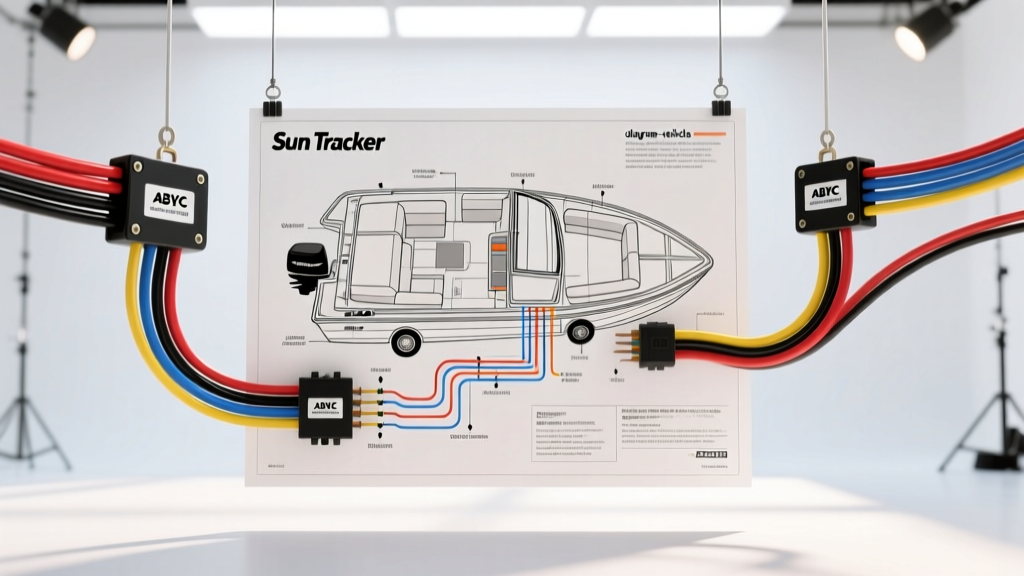
Introduction to Marine DC Electrical Systems
Whether you are troubleshooting a dead battery, replacing a blown fuse, or installing new LED deck lights, understanding the wiring diagram for Sun Tracker pontoon vessels is essential. Unlike automotive electrical systems, marine environments subject your wiring to constant vibration, high humidity, and corrosive elements. A pontoon boat's DC (Direct Current) electrical system typically operates on a 12-volt negative-ground architecture, but the standards governing its construction differ significantly from standard passenger vehicles.
For beginners, looking at a factory schematic can feel like deciphering an alien language. However, by breaking down the fundamentals of marine wiring standards, color codes, and circuit routing, you can confidently navigate your vessel's electrical layout. This guide will teach you how to read your boat's schematics, select the correct wire gauges, and troubleshoot common issues using industry-standard practices.
Schematics vs. Routing Diagrams: What Are You Looking At?
When sourcing documentation from the manufacturer or the New Wire Marine Diagram Library, you will generally encounter two types of visual aids:
- Logical Schematics: These diagrams show the electrical flow from the power source (battery) through the overcurrent protection (fuse/breaker), the switch, and finally to the load (light or pump). They do not represent the physical location of the wires.
- Physical Routing Diagrams: These illustrate how the harness is physically run through the pontoon logs, up into the helm console, and out to the transom. Sun Tracker pontoons typically route the main harness through the port-side pontoon log or a central utility channel to protect it from debris and water intrusion.
For troubleshooting a specific component, always start with the logical schematic to understand the circuit's path, then use the routing diagram to locate the physical connection points.
ABYC Marine Wire Color Code Standards
One of the most critical differences between automotive and marine wiring is the color code standard. While the Society of Automotive Engineers (SAE) dictates car wiring colors, marine vessels in the United States follow the American Boat and Yacht Council (ABYC) E-11 standards. Using standard automotive wire in a pontoon boat is a severe safety hazard, as the untinned copper will quickly oxidize (turn black) and increase resistance, leading to voltage drops and potential electrical fires.
Below is the standard ABYC color code chart you will see reflected in your Sun Tracker wiring diagram:
| Wire Color | ABYC Designation | Common Sun Tracker Application |
|---|---|---|
| Red | Positive Main Power | Battery positive to main breaker panel |
| Yellow | Starter / Alternator | Outboard engine main harness connection |
| Dark Blue | Navigation Lights | Bow and stern running lights |
| Brown | Bilge Pump / Blower | Automatic bilge pump float switch feed |
| Light Blue | Interior / Courtesy Lights | Under-deck LED lighting and cabin dome |
| Black or Yellow w/ Stripe | Ground / Tachometer | Engine block ground to transom, gauge feeds |
Note: Always verify with your specific model year's diagram, as aftermarket accessories installed by dealerships may not adhere strictly to ABYC colors.
Wire Gauge (AWG) and Overcurrent Protection
Marine wiring requires careful calculation of wire gauge (AWG) based not just on the amperage of the load, but on the total length of the wire run. In DC systems, voltage drop is a major concern. The ABYC recommends a maximum 3% voltage drop for critical navigation and communication circuits, and a 10% drop for non-critical loads like interior lighting.
When reading the wiring diagram for Sun Tracker pontoon layouts, use this reference chart to ensure your overcurrent protection (fuses or breakers) matches the wire gauge protecting it:
| Wire Gauge (AWG) | Max Breaker Size | Max Run (ft) at 15A (3% Drop) | Typical Use Case |
|---|---|---|---|
| 16 AWG | 10 Amps | 12 feet | LED indicator lights, small gauges |
| 14 AWG | 15 Amps | 18 feet | Interior courtesy lights, horn |
| 12 AWG | 20 Amps | 28 feet | Navigation lights, 12V accessory receptacles |
| 10 AWG | 30 Amps | 45 feet | Bilge pumps, anchor windlasses (short run) |
| 8 AWG | 40 Amps | 70 feet | Main accessory distribution bus feeds |
Always use marine-grade, tinned copper wire (UL 1426 standard). The tin coating prevents moisture from wicking up inside the wire insulation, a phenomenon known as 'black wire corrosion' that routinely destroys automotive wire used in marine applications.
Decoding the Helm Switch Panel
The helm is the nerve center of your pontoon's electrical system. Sun Tracker typically utilizes Carling Technologies V-Series or Contura rocker switches. When looking at the back of the switch panel on your diagram, you will see terminal pin numbers. Understanding these pins is crucial for replacing a faulty switch:
- Pin 3 (Source): Receives 12V+ from the fused distribution bus.
- Pin 2 (Load): Sends 12V+ out to the accessory (e.g., the bilge pump or navigation lights).
- Pin 1 (Ground): Provides the negative ground path specifically for the switch's internal LED illumination. If your switch doesn't light up at night but the accessory works, Pin 1 or its ground bus connection is the culprit.
Troubleshooting Decision Tree: The Dead Bilge Pump
The bilge pump is a critical safety device. If your wiring diagram shows power leaving the switch but the pump remains silent, follow this expert troubleshooting sequence:
- Check the Float Switch: Manually lift the float switch arm. If the pump engages, the issue is debris blocking the float, not the wiring.
- Test Voltage at the Pump: Set your digital multimeter to DC Volts. Place the red probe on the brown wire terminal at the pump and the black probe on a known clean engine ground. If you read less than 11.5V while the switch is engaged, you have a voltage drop issue in the harness.
- Inspect the Ground Bus: Over 80% of marine electrical failures occur on the ground side. Locate the negative bus bar under the helm. Look for green/white powdery corrosion. Disconnect the ground wire, clean the ring terminal with a wire brush, apply a small amount of dielectric grease to the terminal stud (not the crimp barrel), and re-torque to 15 in-lbs.
- Verify the Inline Fuse: Many Sun Tracker models feature an inline ATC blade fuse holder near the battery for the bilge circuit to ensure it remains 'hot' even when the main battery switch is turned off. Check this fuse for a blown element.
Best Practices for Marine Connections
When repairing or modifying your pontoon's wiring, never use standard vinyl electrical tape or non-ratcheting crimpers. According to BoatUS marine electrical guidelines, all connections must be made using a ratcheting crimping tool to ensure a gas-tight seal between the copper strands and the terminal barrel.
Furthermore, always use adhesive-lined heat shrink terminals (often referred to as marine heat shrink). When heated, the inner lining melts and seals the wire insulation to the terminal barrel, completely blocking moisture intrusion. Standard automotive butt connectors will fail within a single season on a pontoon boat due to the constant flexing of the hull and high ambient humidity.
Summary
Mastering the wiring diagram for Sun Tracker pontoon boats empowers you to maintain your vessel safely and efficiently. By respecting ABYC color codes, calculating AWG requirements based on total circuit length, and utilizing marine-grade tinned copper and adhesive heat shrink, you ensure your electrical system will withstand the harsh marine environment for years to come. Always disconnect the negative battery terminal before performing any work on your DC harness, and consult a certified marine electrician if you encounter complex multiplexed engine data networks.