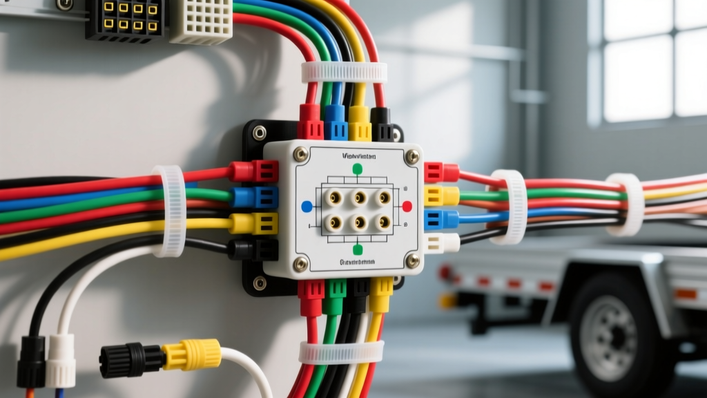
Understanding the Western 6-Pin Connector Standard
When technicians and heavy-duty haulers search for a reliable western 6 pin controller wiring diagram, they are typically dealing with commercial trailers, agricultural equipment, or custom-built flatbeds that utilize the heavy-duty 6-way round connector. Unlike the modern 7-way RV blade standard, the 6-pin round configuration relies on robust, threaded locking mechanisms and heavier gauge wire capacities, making it ideal for high-draw electric brake systems and auxiliary power needs.
Properly installing and wiring a 6-pin harness requires strict adherence to SAE color codes, precise wire stripping, and correct torque specifications on terminal blocks. A poorly executed ground or undersized brake wire will result in voltage drop, weak braking performance, and potential thermal failure at the connector pins.
Standard 6-Way Round Pinout Chart
The following table details the industry-standard pin assignments for the 6-way round connector. Always verify your specific trailer manufacturer's schematic, as some legacy agricultural setups may swap the auxiliary and brake pins.
| Pin Position | Function | Standard Wire Color | Recommended AWG | Max Continuous Load |
|---|---|---|---|---|
| Pin 1 (Ground) | Chassis Ground / Return | White | 10 AWG (or 8 AWG) | 40A |
| Pin 2 (Tail) | Tail, License, Marker Lights | Brown | 12 AWG | 15A |
| Pin 3 (Left) | Left Turn / Stop Lamp | Yellow | 12 AWG | 15A |
| Pin 4 (Right) | Right Turn / Stop Lamp | Green | 12 AWG | 15A |
| Pin 5 (Brakes) | Electric Trailer Brakes | Blue | 10 AWG | 30A |
| Pin 6 (Aux) | 12V Auxiliary / Battery Charge | Red or Black | 10 AWG | 30A |
Reference: Pinout configurations align with legacy heavy-duty standards and guidelines documented in the etrailer.com 6-Way Wiring FAQ and CURT Manufacturing Technical Library.
Pre-Installation: Tools and Material Specifications
Before cutting into your existing harness or routing new lines through the trailer tongue, gather the correct materials. Using automotive-grade, adhesive-lined components is non-negotiable for preventing corrosion in the connector housing.
- Wire: SAE J1128 compliant cross-linked polyethylene (XLPE) jacketed copper wire. Avoid CCA (Copper Clad Aluminum) wire, as it suffers from higher resistance and brittle failure modes under vibration.
- Terminals: #10 and #12 AWG heat-shrink ring terminals with a 3:1 shrink ratio. The inner adhesive layer must melt and seal the wire strands upon heating.
- Crimping Tool: Ratcheting terminal crimper with dedicated nests for 12-10 AWG insulated terminals. Do not use standard pliers, which deform the terminal barrel and reduce pull-out strength.
- Corrosion Inhibitor: NO-OX-ID A-Special or high-quality dielectric grease for the male/female pin mating surfaces.
- Fasteners: Stainless steel self-tapping screws (minimum #12) with star washers for frame grounding.
Step-by-Step Wiring & Routing Guide
- Route the Main Harness: Feed the 6-pin pigtail through the trailer tongue. Maintain a minimum clearance of 6 inches from any exhaust components on the tow vehicle to prevent the XLPE jacket from melting. Secure the harness to the frame every 18 inches using UV-resistant nylon cable ties with stainless steel mounting bases.
- Establish the Master Ground (Pin 1): The white ground wire is the most critical circuit. Strip exactly 3/8 inch of insulation from the 10 AWG white wire. Crimp a #10 ring terminal using the ratcheting crimper. Sand the trailer frame down to bare, shiny metal at the grounding point. Apply the ring terminal, secure with a #12 stainless screw and star washer, and torque to 15-20 in-lbs. Coat the terminal with dielectric grease after tightening.
- Terminate the Lighting Circuits (Pins 2, 3, 4): Strip and crimp the brown, yellow, and green 12 AWG wires to their respective junction block terminals. If using a standard trailer junction box, ensure the set screws are tightened to 12 in-lbs to prevent the wire from pulling out under road vibration.
- Wire the Electric Brakes (Pin 5): Route the 10 AWG blue wire down the trailer frame to the brake assemblies. At each axle, use a sealed, adhesive-lined butt splice to branch the blue wire to the left and right brake magnets. Ensure the brake magnet ground wires (usually white) are grounded independently to the axle flange or main frame, never daisy-chained back to the brake controller ground.
- Connect the Auxiliary Power (Pin 6): Route the 10 AWG red/black wire to the trailer's breakaway battery or interior 12V distribution block. Install a 30A auto-reset circuit breaker within 18 inches of the battery positive terminal to protect against dead shorts in the event of a wire chafe.
Integrating the Brake Controller in the Tow Vehicle
The western 6 pin controller wiring diagram is only half the equation; the tow vehicle must be wired to supply proportional power to Pin 5. Modern proportional brake controllers (e.g., Tekonsha Prodigy, Redarc Tow-Pro) require four specific connections:
- White (Ground): Ring terminal directly to the vehicle chassis or negative battery post. (10 AWG).
- Black (12V Power): Routed directly to the positive battery terminal via a 30A or 40A auto-reset breaker. (10 AWG).
- Red (Stoplight Switch): Spliced into the vehicle's dedicated stoplight circuit. Use a digital multimeter to verify this wire only shows 12V when the brake pedal is depressed, and 0V during cruise or turn signal activation. Splicing into the wrong circuit (like a combined turn/brake wire) will cause the controller to apply trailer brakes during turns.
- Blue (Brake Output): This wire routes to the tow vehicle's 6-pin receptacle (Pin 5). Use a minimum of 10 AWG wire for the run from the controller to the rear bumper to minimize voltage drop under heavy braking loads.
Real-World Troubleshooting & Failure Modes
Even with a perfect western 6 pin controller wiring diagram reference, environmental factors and mechanical stress can cause faults. Use this diagnostic matrix to resolve common issues:
| Symptom | Probable Cause | Diagnostic Action & Fix |
|---|---|---|
| Trailer brakes pulse or lock up during turns | Brake controller Red wire spliced to combined stop/turn circuit | Test Red wire with multimeter. Relocate splice to a dedicated CHMSL (Center High Mount Stop Lamp) wire or dedicated brake switch circuit. |
| Dim marker lights; brake controller shows 'Overload' or 'Short' | High resistance on Pin 1 (Ground) or undersized ground wire | Measure voltage drop between trailer frame and tow vehicle battery negative. If >0.2V, clean frame ground point and upgrade to 8 AWG ground wire. |
| Auxiliary battery not charging; Pin 6 melts | Missing inline breaker or parasitic short in breakaway switch | Inspect 10 AWG Aux wire for chafing near the tongue jack. Verify 30A breaker is installed. Test breakaway switch for internal short. |
| Brakes engage weakly even at max controller gain | Voltage drop on Pin 5 (Blue wire) due to distance/gauge | Measure voltage at controller blue output vs. voltage at trailer brake magnet. If drop >1.5V, replace blue wire run with 8 AWG. |
For advanced diagnostics regarding commercial vehicle wiring standards and voltage drop tolerances, consult the baseline specifications outlined by SAE International.
Final Inspection Protocol
Before connecting the trailer to the tow vehicle, perform a continuity check on all circuits using a digital multimeter. Verify that Pin 1 shows less than 0.5 ohms of resistance to the trailer chassis. Once connected, activate the manual override lever on the brake controller to 100% output and use an infrared thermometer to check the 6-pin connector housing. Temperatures exceeding 140°F (60°C) at the pins indicate poor crimps, loose terminal block screws, or undersized wiring that must be addressed before highway towing.