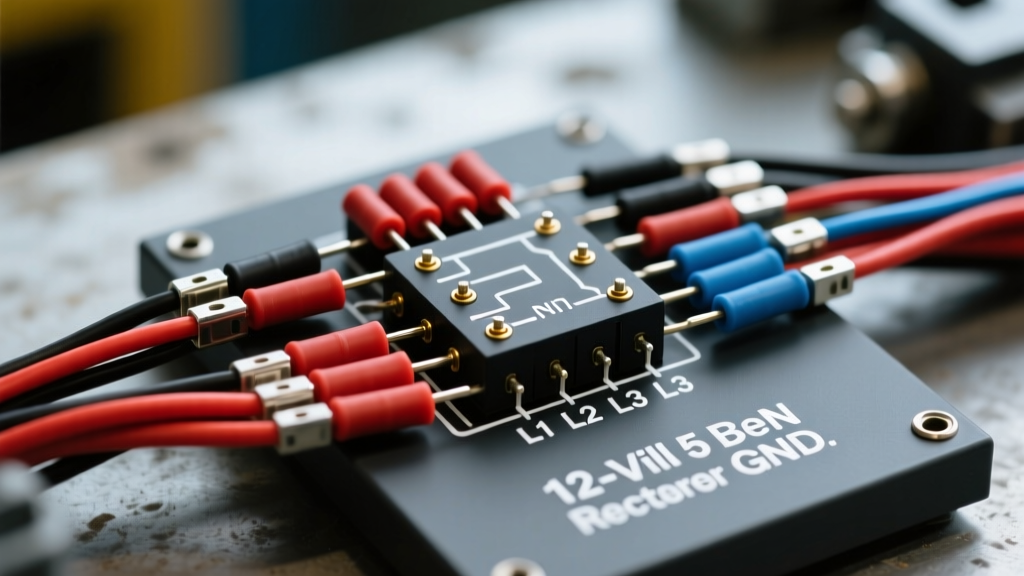
Auxiliary Power Integration for Trailers
Integrating an onboard auxiliary generator into a heavy-duty utility, mobile command, or camper trailer requires a robust charging system. This system must maintain the trailer's house battery bank, power high-draw electric winches, and ensure the electric brake breakaway safety system remains fully charged independent of the tow vehicle. Because most auxiliary trailer generators (such as customized Honda GX-series engines or integrated Onan RV gensets) utilize 3-phase stators to produce raw AC power, you must convert this output to stable DC. This necessitates a precise 12 volt 5 pin regulator rectifier wiring diagram tailored for high-vibration, mobile environments.
Unlike standard automotive alternators with internal regulators, auxiliary trailer stators require an external shunt-style or MOSFET regulator/rectifier. The 5-pin configuration is the industry standard for modern 3-phase small engine charging systems, offering superior heat dissipation and a stable 14.2V–14.4V output required to safely charge AGM, Gel, or Lithium Iron Phosphate (LiFePO4) trailer batteries. Adhering to SAE J1128 standards for low-tension primary cable is critical when routing these harnesses along the trailer chassis.
12 Volt 5 Pin Regulator Rectifier Wiring Diagram Walkthrough
The following walkthrough details the exact pinout, wire routing, and termination procedures required to safely integrate a 5-pin regulator into a trailer's auxiliary electrical architecture. This setup assumes a standard 3-phase stator outputting between 15 and 30 Amps at peak RPM.
Pinout Matrix and Wire Color Codes
While aftermarket manufacturers occasionally deviate, the universal standard for a 5-pin MOSFET regulator rectifier (such as the FH012AA or SH775 equivalents commonly used in trailer genset builds) follows the color matrix below. Always verify with your specific stator manufacturer's documentation before applying power.
| Pin Number | Function | Standard Wire Color | Connection Destination | Recommended AWG |
|---|---|---|---|---|
| 1 | AC Phase A | Yellow | Stator Wire 1 | 12 AWG |
| 2 | AC Phase B | Yellow | Stator Wire 2 | 12 AWG |
| 3 | AC Phase C | Yellow | Stator Wire 3 | 12 AWG |
| 4 | DC Output (+) | Red | Battery Positive / Busbar | 10 AWG |
| 5 | DC Ground (-) | Black or Green | Battery Negative / Chassis | 10 AWG |
Step-by-Step Harness Routing and Termination
- Stator to Regulator (AC Side): Route the three Yellow wires from the stator housing to the regulator. It is imperative that all three AC wires are cut to the exact same length and use the same gauge (12 AWG). Unequal lengths create resistance imbalances across the 3-phase load, leading to premature diode failure inside the rectifier. Terminate using heat-shrink butt splices or Deutsch DT 6-way connectors for weatherproofing.
- Regulator to Battery (DC Positive): Run a 10 AWG Red wire from Pin 4 to the trailer’s auxiliary battery positive terminal or main distribution busbar. You must install a 30A or 40A MAXI fuse holder within 6 inches of the battery positive post to protect the harness from catastrophic short circuits in the event of a trailer collision or wire chafing.
- Regulator Ground (DC Negative): Run a 10 AWG Black/Green wire from Pin 5 directly to the battery negative terminal or a dedicated, bare-metal grounding busbar. Do not rely solely on the trailer chassis for the regulator ground. Trailers suffer from significant ground path voltage drop due to rusty hinges, pivoting tongues, and painted surfaces. A poor ground will cause the regulator to misread the system voltage, resulting in severe overcharging and battery thermal runaway.
AWG Sizing and Overcurrent Protection
Trailer environments expose wiring to high ambient heat (especially near generator exhaust routing) and continuous vibration. According to RVIA electrical standards and general marine/RV wire derating charts, you must size your wire not just for the amperage, but for the length of the run to prevent voltage drop. The DC side of the regulator is particularly sensitive; a voltage drop on the ground wire will cause the regulator to push higher voltages to compensate, boiling lead-acid batteries or triggering BMS shutdowns on lithium banks.
| Max Stator Output | Total DC Run Length (Round Trip) | Minimum DC Wire Gauge (AWG) | Fuse Rating (MAXI/ANL) |
|---|---|---|---|
| 15 Amps | Under 5 Feet | 12 AWG | 20A |
| 20 Amps | 5 to 10 Feet | 10 AWG | 30A |
| 30 Amps | 10 to 15 Feet | 8 AWG | 40A |
| 45+ Amps | Over 15 Feet | 6 AWG | 60A ANL |
Isolation Relays: Preventing Tow Vehicle Backfeed
When wiring a trailer with an onboard generator and a 5-pin regulator, you must integrate an isolation relay to prevent the trailer's auxiliary charging system from backfeeding into the tow vehicle’s alternator when connected via a standard 7-pin RV blade connector. If the trailer's regulator outputs 14.4V and the tow vehicle's alternator is outputting 14.2V, the trailer will attempt to charge the truck, potentially damaging the truck's voltage regulator or causing a wiring harness fire on the trailer tongue.
Relay Wiring Logic (Bosch-Style 12V 4-Pin Relay):
- Pin 30 (Common): Connect to the 12V Auxiliary Power pin on the trailer's 7-way plug (Pin 4).
- Pin 87 (Normally Open): Connect to the trailer's main 12V distribution busbar.
- Pin 86 (Coil Power): Connect to the trailer's 12V auxiliary battery positive (fused at 5A).
- Pin 85 (Coil Ground): Connect to the 12V Ground pin on the trailer's 7-way plug (Pin 1).
How it works: The trailer's onboard generator only connects to the trailer's 12V accessories and breakaway battery when the tow vehicle is running and sending 12V through the 7-pin auxiliary circuit, energizing the relay coil and bridging Pin 30 to 87. When you disconnect the trailer, the relay opens, isolating the systems.
Thermal Management and Ground Path Voltage Drop
The most common cause of 5-pin regulator rectifier failure in trailer applications is thermal mismanagement. Shunt-style regulators dissipate excess stator energy as heat. Never mount the regulator inside an enclosed trailer tongue box, battery compartment, or directly above the generator exhaust manifold. The unit requires ambient airflow. Mount it vertically on an open trailer crossmember using stainless steel hardware, applying dielectric grease to the connector cavity to prevent moisture ingress from road spray.
Diagnosing Stator and Regulator Failure Modes
When troubleshooting auxiliary trailer charging systems, technicians should refer to comprehensive stator and rectifier testing guides utilizing a digital multimeter (DMM). Follow this diagnostic decision tree:
- Symptom: Battery reads 12.6V at rest, but drops to 11V while generator is at high RPM.
Cause: Open circuit in the stator or blown AC phase.
Fix: Set DMM to AC Volts. Probe the three Yellow wires at the stator connector (engine running). You should read 20V-50V AC between any two Yellow wires. If one pair reads 0V, the stator is burnt out and requires replacement. - Symptom: Battery overcharges past 15V, boiling electrolyte or triggering BMS faults.
Cause: Voltage drop on the DC Ground wire (Pin 5).
Fix: Set DMM to DC Volts. Place the black probe on the battery negative terminal and the red probe on the regulator's metal casing or Pin 5 ground wire. If you read more than 0.1V drop while the generator is running, your ground path has excessive resistance. Clean the chassis ground point to bare metal, apply anti-oxidant paste, and torque the M8 grounding bolt to 15 Nm. - Symptom: Regulator casing is too hot to touch, melting the connector pigtails.
Cause: Shorted battery cell or massive parasitic draw forcing the regulator into 100% duty cycle.
Fix: Disconnect the Red DC output wire. If the regulator cools down but the stator still produces AC voltage, the trailer battery is internally shorted and must be replaced immediately.
Summary of Best Practices
Successfully deploying a 12 volt 5 pin regulator rectifier wiring diagram on a trailer requires respecting the harsh mobile environment. By utilizing equal-length AC stator wires, oversizing the DC ground path to eliminate voltage drop, and integrating an isolation relay to protect the tow vehicle, you ensure that your trailer's auxiliary power system remains reliable, safe, and capable of supporting critical systems like electric brakes and heavy-duty winches under any operating condition.