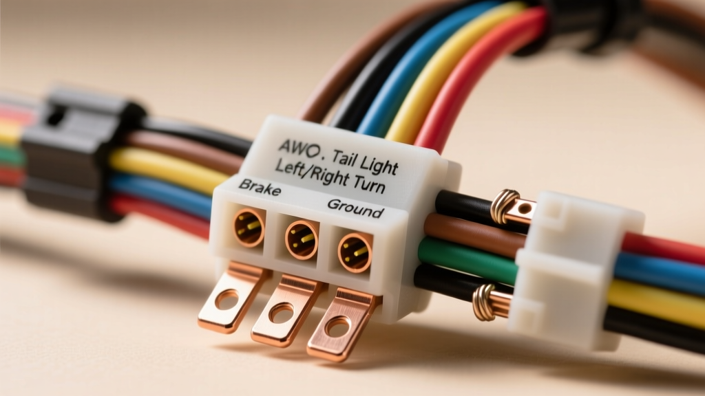
Understanding the 4-Way Flat to 7-Way RV Blade Adaptation
Upgrading a tow vehicle's electrical interface from a standard 4-pin flat connector to a 7-pin RV blade is a critical modification for hauling heavy-duty trailers, fifth wheels, and campers. While a simple plug-and-play 4 pin to 7 pin adapter wiring diagram might suggest a direct translation, the reality of automotive electrical systems requires a deeper integration. The 4-pin flat connector is strictly limited to basic illumination: running lights, left turn/stop, right turn/stop, and a shared ground. The 7-way RV blade (governed by SAE J286 standards) introduces three high-current circuits: electric trailer brakes, 12V auxiliary power, and reverse lights.
If your vehicle did not come equipped with a factory tow package, simply plugging in a molded plastic adapter will leave the brake, auxiliary, and reverse circuits completely dead. To achieve full functionality, you must utilize a hardwired adapter pigtail and manually route the missing circuits from the vehicle's front power sources and brake controller to the rear bumper. This technical reference provides the exact pinout matrix, AWG requirements, and diagnostic procedures for executing a flawless 4-to-7 pin conversion.
Core 4-Pin to 7-Pin RV Blade Pinout Matrix
The foundation of any trailer wiring project is understanding the color-code translation between the two connector styles. While the lighting circuits share identical functions, the physical pin locations and wire gauges differ significantly. The following matrix outlines the direct mapping required when splicing a 4-way flat harness into a 7-way RV blade socket.
| Pin Position (7-Way) | Circuit Function | 4-Pin Flat Color | 7-Pin RV Color | Min. AWG |
|---|---|---|---|---|
| Pin 1 (Bottom) | Left Turn / Stop | Yellow | Yellow | 14 AWG |
| Pin 2 (Top Left) | Reverse Lights / Aux | N/A | Purple | 12 AWG |
| Pin 3 (Top Right) | Ground | White | White | 8 AWG |
| Pin 4 (Center) | Right Turn / Stop | Green | Green | 14 AWG |
| Pin 5 (Bottom Left) | Electric Brakes | N/A | Blue | 10 AWG |
| Pin 6 (Bottom Right) | Tail / Running Lights | Brown | Brown | 14 AWG |
| Pin 7 (Top Center) | 12V Auxiliary Power | N/A | Black | 10 AWG |
Hardwiring the Missing Circuits: Brakes, Aux, and Reverse
When adapting a 4-pin system to a 7-pin system, the lighting circuits (Brown, Yellow, Green) can be spliced directly into the existing 4-pin flat harness using heat-shrink butt connectors. However, the three missing circuits require dedicated wiring runs from the engine bay to the rear bumper. According to etrailer.com wiring guidelines, failing to properly fuse and gauge these extended runs is the leading cause of trailer electrical fires and component failure.
Sourcing the Brake Controller Output (Blue Wire)
The blue wire carries the modulated DC voltage from the in-cab brake controller to the trailer's electric brake magnets. Because brake magnets can draw up to 12 amps per axle, a dual-axle trailer will pull roughly 24 amps under maximum braking force. You must run a dedicated 10 AWG blue wire from the brake controller's blue output lead, through the firewall, and down the vehicle's frame rail to the 7-pin socket. This circuit must be protected by a 30A auto-reset circuit breaker mounted within 18 inches of the battery or the controller's power source. Never route the blue wire parallel to the vehicle's ABS sensor wiring or high-voltage ignition coils, as the PWM (Pulse Width Modulation) signal from the brake controller can induce electromagnetic interference (EMI) in sensitive vehicle computers.
Integrating the 12V Auxiliary Power (Black Wire)
The black wire provides a constant 12V feed to the trailer, used for charging breakaway batteries, powering interior lights, or running 12V compressor refrigerators. Voltage drop is the primary enemy of long DC wire runs. A 20-foot run of 12 AWG wire carrying 15 amps will experience a voltage drop that can starve trailer appliances of necessary amperage. Therefore, you must use a minimum of 10 AWG (preferably 8 AWG for runs exceeding 20 feet) stranded copper wire. Connect this wire directly to the vehicle's battery positive terminal via a 40A auto-reset circuit breaker. Do not tap into the vehicle's rear 12V accessory outlets, as they are typically limited to 10A-15A and will blow the interior fuse panel.
Wire Gauge (AWG) and Terminal Crimp Specifications
Proper terminal selection is just as critical as wire sizing. Vibration and moisture at the rear bumper will quickly destroy poorly crimped connections. Always use adhesive-lined heat shrink ring terminals and a ratcheting crimp tool to ensure a gas-tight mechanical bond.
| Wire Gauge | Circuit Application | Terminal Type | Crimp Die Color | Torque Spec (Chassis Ground) |
|---|---|---|---|---|
| 8 AWG | Main Ground (White) | Heat Shrink Ring (#10 stud) | Red | 15-20 ft-lbs |
| 10 AWG | Brakes (Blue) / Aux (Black) | Heat Shrink Butt / Ring | Blue | N/A |
| 12 AWG | Reverse Lights (Purple) | Heat Shrink Butt | Blue | N/A |
| 14-16 AWG | Lighting (Brown, Yellow, Green) | Heat Shrink Butt | Yellow | N/A |
Common Failure Modes and Multimeter Diagnostics
Even with a perfect 4 pin to 7 pin adapter wiring diagram, environmental factors and installation errors can lead to circuit degradation. Use a digital multimeter (DMM) and a 7-pin circuit tester to diagnose the following common failure modes.
Symptom: Trailer Brakes Pulse or Fail to Engage
Cause: Voltage drop on the blue wire or a high-resistance ground loop. If the 7-pin ground (White) is corroded, the brake current will attempt to backfeed through the lighting ground paths, causing erratic brake behavior.
Diagnostic Fix: Set your DMM to DC Volts. Probe the blue wire at the 7-pin socket while an assistant applies the manual override lever on the brake controller. You should read within 0.5V of the battery voltage (approx 12.1V - 12.6V). If you read below 10V, inspect the inline 30A breaker for corrosion and verify the white ground wire is secured to bare, unpainted chassis metal.
Symptom: 12V Fridge Won't Charge on Trailer
Cause: Undersized black auxiliary wire or a tripped inline breaker. Many DIY installers mistakenly use 14 AWG wire for the 12V aux circuit, resulting in a massive voltage drop over the length of the vehicle.
Diagnostic Fix: Measure the voltage at the vehicle's battery (Pin 7 reference ground). Then, measure the voltage at the trailer's battery connection. A drop greater than 0.8V under load indicates the wire gauge is insufficient. Upgrade the black wire to 8 AWG and apply dielectric grease to the 7-pin socket contacts to prevent galvanic corrosion.
Symptom: Turn Signals Backfeed into Running Lights
Cause: Ground loop caused by a shared, corroded ground point. When the white ground wire fails, the left turn signal current seeks a path to ground through the brown (running light) wire, causing the trailer's running lights to flash in unison with the turn signal.
Diagnostic Fix: Disconnect the 7-pin connector. Use the continuity setting on your multimeter to test between the white wire pin and the vehicle's bare chassis. If resistance is above 0.5 ohms, remove the ground ring terminal, sand the chassis mounting point down to bare steel, reattach the terminal, and coat with anti-corrosion battery spray.
For comprehensive installation manuals and vehicle-specific brake controller wiring ports, always consult Tekonsha brake controller wiring resources and your vehicle manufacturer's upfitter body builder guidelines. Proper execution of this 4-to-7 pin adaptation ensures safe, legal, and reliable towing for years to come.