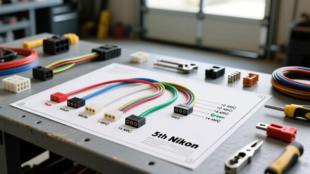
Introduction to 5th Wheel Electrical Architecture
Unlike lightweight bumper-pull campers, a 5th wheel trailer presents unique electrical routing challenges. The distance from the pin box (where the 7-way connector resides) to the rear axle brakes and tail lights often exceeds 35 to 45 feet. This extended cable run makes voltage drop a critical factor in your 5th wheel trailer wiring diagram. Furthermore, modern 5th wheels draw substantial amperage to support residential refrigerators, multiple slide-out motors, and lithium battery bank charging. Understanding the exact pinout, wire color codes, and American Wire Gauge (AWG) requirements is essential for safe towing and reliable electrical operation.
The 7-Pin RV Blade Connector: Pinout and Wire Color Standards
The standard 7-way RV blade connector is governed by the RVIA (Recreation Vehicle Industry Association) and aligns with SAE J286 standards for truck-trailer electrical connections. Below is the definitive pinout chart for a standard 5th wheel application.
| Pin | Function | RVIA Wire Color | Minimum AWG | Max Continuous Amps |
|---|---|---|---|---|
| 1 | Ground (Chassis) | White | 10 AWG | 40A |
| 2 | Electric Brakes | Blue | 10 AWG | 20A |
| 3 | Tail / Running Lights | Green | 14 AWG | 10A |
| 4 | 12V Auxiliary / Battery Charge | Black | 10 AWG | 30A |
| 5 | Left Turn / Stop | Red | 14 AWG | 10A |
| 6 | Right Turn / Stop | Brown | 14 AWG | 10A |
| 7 | Reverse / Auxiliary | Yellow | 14 AWG | 10A |
Deep Dive: Critical Circuit Routing and AWG Specifications
Pin 1 & 4: Ground and 12V Auxiliary Power
The White (Ground) and Black (12V Aux) wires are the heavy lifters of your 5th wheel trailer wiring diagram. The white wire must be a minimum of 10 AWG, bonded directly to the trailer's main chassis frame near the junction box. Do not rely solely on the hitch ball or kingpin for grounding; mechanical connections are prone to grease, rust, and high resistance, which will cause erratic brake controller behavior and dim lighting. The black 12V auxiliary wire is responsible for charging the trailer's deep-cycle or lithium battery bank while driving. Because alternators can output 30+ amps to a depleted battery, upgrading this run from the standard 10 AWG to 8 AWG is a common modification for 5th wheels equipped with large lithium banks to prevent the wire from overheating and to minimize voltage drop over the 40-foot run.
Pin 2: Electric Brakes and PWM Signals
The Blue wire carries the Pulse Width Modulation (PWM) signal from your tow vehicle's brake controller to the trailer's electric brake magnets. A standard tandem-axle 5th wheel has four brake magnets. Each magnet typically measures between 10 and 12 ohms. Wired in parallel, the total circuit resistance drops to roughly 2.5 to 3.0 ohms. At 12 volts, this results in a current draw of 4 to 5 amps. While 12 AWG wire might theoretically handle this amperage, the Tekonsha installation guidelines strongly recommend 10 AWG for the main brake feed line. If voltage drop occurs due to undersized wire or poor splices, the rear-most brake magnets will receive less voltage than the front magnets, leading to uneven braking, trailer sway, and premature magnet wear.
Pins 3, 5, 6, & 7: Lighting and Signal Circuits
The Green, Red, Brown, and Yellow wires handle the lighting circuits. Factory diagrams typically specify 14 AWG or even 16 AWG for these circuits. However, if your 5th wheel has not been upgraded to LED lighting, the incandescent bulbs draw significant current. A single incandescent 1157 dual-filament bulb draws roughly 2.1 amps on the running light circuit. With multiple clearance lights, tail lights, and license plate lights, the Green (Tail) wire can easily approach 8 amps. Upgrading to LED assemblies reduces this draw to less than 1 amp total, virtually eliminating voltage drop and melted sockets.
The 5th Wheel Junction Box: Termination Walkthrough
Inside the pin box of your 5th wheel, you will find the main electrical junction box. This is where the external 7-way pigtail meets the internal trailer harness. Proper termination here is the difference between a reliable trip and a roadside electrical failure.
- Strip and Crimp: Strip exactly 3/8 inch of insulation from the 10 AWG and 14 AWG wires. Use a ratcheting crimper to attach #10 closed-end ring terminals. Never use fork terminals in a high-vibration environment like a pin box; ring terminals ensure the wire cannot slip off the terminal block screw.
- Barrier Strip Routing: Follow the internal diagram stamped on the junction box cover. Ensure the Blue (Brake) wire is routed to the terminal that feeds the underbelly brake harness, keeping it isolated from the 12V Black wire to prevent short circuits.
- Corrosion Prevention: Apply a small amount of No-Ox-Id or dielectric grease to the brass terminal screws before tightening. The pin box is highly susceptible to road spray and condensation. Galvanic corrosion between copper wire and steel screws will create a high-resistance bottleneck that mimics a blown fuse.
Advanced Modification: Bypassing the 7-Pin for High-Amp Solar
Many modern 5th wheel owners are installing 400W+ solar arrays and DC-DC chargers. The standard 7-pin Black wire (10 AWG) is a bottleneck for high-amperage alternator charging. A common advanced modification to the standard 5th wheel trailer wiring diagram is the addition of an Anderson Powerpole SB50 connector mounted flush on the pin box. This allows the use of 6 AWG or 4 AWG wires directly from the truck's alternator/battery to the trailer's DC-DC charger, completely bypassing the 7-way plug for heavy charging duties while retaining the 7-way for standard lighting and braking.
Troubleshooting Decision Tree: Common 5th Wheel Wiring Failures
When your 5th wheel exhibits electrical gremlins, use this symptom-cause-fix decision tree to isolate the fault:
- Symptom: Brake controller displays 'S.H.' (Short Circuit) or 'O.L.' (Overload) when pressing the manual override.
Cause: The Blue brake wire has chafed against the chassis frame inside the underbelly coroplast, or a brake magnet has failed internally and shorted to the backing plate.
Fix: Disconnect the 7-way plug. Use a multimeter to test resistance between Pin 2 (Blue) and Pin 1 (White) on the trailer side. A reading near 0 ohms indicates a dead short. Inspect the underbelly wire loom and drop the brake drums to test individual magnets (should read ~12 ohms each). - Symptom: Tail lights glow dimly, and the marker lights flicker when the turn signal is engaged.
Cause: A classic 'bad ground' or voltage bleed. The White ground wire has corroded at the junction box, forcing the return current to backfeed through the turn signal filaments to find a path to the truck chassis.
Fix: Clean the main chassis ground lug with a wire brush, apply dielectric grease, and retorque. Verify continuity from the trailer chassis to the White wire at the junction box. - Symptom: Trailer batteries are not charging while driving, despite a good alternator.
Cause: Voltage drop on the Black 12V wire due to the 40-foot distance, or a blown inline fusible link near the truck's battery.
Fix: Measure voltage at the truck's Pin 4 (should be ~13.8V). Then measure at the trailer's junction box Black wire terminal. If the trailer side reads below 12.5V, the 10 AWG wire is undersized for the amperage draw, or there is severe corrosion at the 7-way blade plug. Upgrade to 8 AWG or install the Anderson SB50 bypass.
For further technical specifications on heavy-duty towing connectors, refer to the Recreation Vehicle Industry Association (RVIA) technical bulletins regarding low-voltage DC wiring standards in recreational vehicles.